2011 Hyundai Sonata Factory Amp Wiring Diagram
Alright, let's dive into the 2011 Hyundai Sonata factory amplifier wiring diagram. This isn't just a random set of lines and colors; it's the roadmap to your car's audio system. Whether you're dealing with a blown speaker, planning an aftermarket upgrade, or just curious about how it all fits together, understanding this diagram is crucial.
Purpose of the Wiring Diagram
Why bother with this diagram? Simple. It's the key to diagnosing audio problems and safely modifying your system. Forget guessing which wire does what! With the factory wiring diagram, you can:
- Troubleshoot audio issues: Identify shorts, opens, and misconnections in the amplifier and speaker circuits.
- Install aftermarket components: Integrate new head units, amplifiers, and speakers without butchering the factory wiring.
- Understand the system's architecture: Learn how the factory amplifier interacts with the head unit and speakers.
- Perform repairs confidently: Fix broken wires and connectors with accuracy.
Key Specs and Main Parts
The 2011 Sonata's factory amplifier is usually located under the passenger seat or in the rear deck area. It's responsible for taking the low-level audio signal from the head unit and boosting it to a level that can drive the speakers. The diagram will outline the connections for the following crucial components:
- Head Unit: The source of the audio signal. The diagram will show the connections from the head unit to the amplifier, including the remote turn-on wire.
- Amplifier: The heart of the system, responsible for amplifying the audio signal. Pay close attention to the power, ground, and signal input/output pins.
- Speakers: The output devices that produce sound. The diagram will illustrate the wiring to each speaker, including polarity (positive and negative).
- Power Source: The battery and the fuse that protects the amplifier. The diagram clearly shows the main power wire from the battery to the amp, and the location of the inline fuse.
- Ground: The crucial grounding point for the amplifier. A poor ground can cause all sorts of audio problems.
The diagram usually includes specifications such as:
- Wire Gauge: The thickness of the wire, typically measured in AWG (American Wire Gauge). Knowing the gauge is important when replacing or extending wires.
- Fuse Rating: The amperage rating of the fuse protecting the amplifier. Using the wrong fuse can lead to damage or fire.
- Connector Types: Identifying the specific connectors used in the system helps you find compatible adapters or replacement parts.
Understanding the Symbols
A wiring diagram uses standardized symbols to represent different components and connections. Here's a breakdown of what you might encounter:
- Solid Lines: Represent wires. The thickness of the line might indicate the wire gauge.
- Dashed Lines: Often indicate shielded wires or connections related to grounding.
- Arrows: Show the direction of current flow.
- Color Codes: Each wire is assigned a specific color (e.g., red, black, blue, yellow). These colors are critical for identifying the correct wire. The diagram will usually include a color code chart.
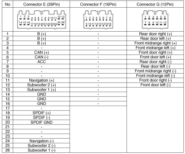
- Connector Symbols: Rectangles or circles with numbers inside represent connectors. The numbers indicate the pin numbers within the connector.
- Ground Symbol: Typically a series of horizontal lines or a downward-pointing triangle.
- Speaker Symbol: A circle with a plus (+) and minus (-) sign indicates a speaker.
- Fuse Symbol: A jagged line inside a rectangle represents a fuse.
Understanding the color codes is especially important. For example, "BLU/RED" indicates a blue wire with a red stripe. Always double-check the color code chart on the diagram to avoid mistakes.
How It Works: Tracing the Signal
Let's trace the audio signal from the head unit to the speakers. The head unit outputs a low-level audio signal. This signal travels through the input wires to the amplifier. The amplifier then increases the amplitude of this signal, providing more power to drive the speakers.
The amplifier needs both a power source (typically a direct connection to the battery) and a ground connection to operate correctly. The remote turn-on wire from the head unit signals the amplifier to power on when the head unit is turned on. This prevents the amplifier from draining the battery when the car is off.
From the amplifier, the amplified audio signals travel to each speaker through individual speaker wires. Each speaker has a positive and a negative terminal; maintaining the correct polarity is crucial for proper sound reproduction. If the polarity is reversed on one speaker, it can cause phase cancellation, resulting in poor bass response.
Real-World Use: Basic Troubleshooting
The wiring diagram is invaluable for troubleshooting audio problems. Here are a few scenarios:
- No sound from one speaker: Use the diagram to trace the speaker wire from the amplifier to the speaker. Check for breaks, shorts, or loose connections. Use a multimeter to test the wire's continuity.
- Weak sound from all speakers: Check the amplifier's power and ground connections. Use a multimeter to verify that the amplifier is receiving the correct voltage and that the ground connection is solid. Also, check the remote turn-on wire.
- Distorted sound: Could be caused by a damaged speaker or a faulty amplifier. Use the diagram to isolate the problem component.
- Amplifier keeps blowing fuses: Indicates a short circuit in the amplifier's power circuit or within the amplifier itself. Carefully inspect the wiring for any exposed wires touching the chassis. If the wiring is intact, the amplifier may need to be replaced.
When troubleshooting, always start with the simplest checks first: fuses, connections, and wire integrity. Use a multimeter to measure voltage, resistance, and continuity. A basic understanding of electrical circuits is essential for safe and effective troubleshooting.
Safety First: Highlighting Risky Components
Working with car audio systems involves electricity, so safety is paramount. Here are some critical safety considerations:
- Disconnect the Battery: Always disconnect the negative terminal of the battery before working on any electrical components. This prevents accidental shorts and potential electrocution.
- Fuses: Never replace a fuse with a higher amperage rating than specified. Doing so can overload the circuit and cause a fire.
- Airbags: Be extremely careful when working near airbag modules. Accidental deployment can cause serious injury. Consult the vehicle's service manual for proper airbag disabling procedures.
- Capacitors in the Amplifier: Amplifiers contain capacitors that can store a significant amount of electrical charge even after the battery is disconnected. Wait a few minutes after disconnecting the battery before touching any internal components of the amplifier.
- Wiring: Always use properly insulated wiring and connectors. Avoid using damaged or frayed wires.
Working with electrical components can be dangerous. If you are not comfortable performing these tasks, consult a qualified car audio technician.
With the 2011 Hyundai Sonata Factory Amp Wiring Diagram in hand, you can confidently diagnose, repair, and upgrade your car's audio system. Understanding the diagram's symbols, tracing the signal flow, and prioritizing safety will empower you to tackle any audio-related project.
We have the full high-resolution wiring diagram available for download. This will give you an even clearer view of the connections and color codes, making your troubleshooting and installation tasks much easier.