2011 Nissan Altima Fuse Box Diagram
The 2011 Nissan Altima fuse box diagram is an indispensable tool for any intermediate car owner, DIY mechanic, or modder looking to understand, maintain, or modify their vehicle's electrical system. Think of it as the Rosetta Stone for your Altima's electrical workings. Without it, diagnosing electrical problems becomes a frustrating exercise in guesswork. With it, you can confidently tackle repairs, install aftermarket accessories, and gain a deeper understanding of how your car functions.
Purpose of the Fuse Box Diagram
Why is this diagram so important? Several reasons:
- Troubleshooting Electrical Problems: A blown fuse is often the culprit behind a malfunctioning component – a headlight that won't turn on, a radio that's silent, or a power window that refuses to budge. The diagram identifies the specific fuse responsible for that circuit, allowing you to quickly pinpoint and replace the blown fuse.
- Installing Aftermarket Accessories: Adding a new stereo, amplifier, lighting system, or other electrical accessory requires tapping into the car's power supply. The diagram helps you identify suitable circuits for drawing power and choosing appropriate fuse ratings to protect the new accessory and the existing vehicle wiring.
- Understanding Vehicle Systems: Even if you're not facing a specific problem, studying the diagram gives you a better understanding of how the various electrical systems in your Altima are interconnected. This knowledge can be invaluable for preventative maintenance and future modifications.
- Avoiding Costly Repairs: By diagnosing and fixing minor electrical issues yourself, you can save significant money on mechanic fees.
Key Specs and Main Parts
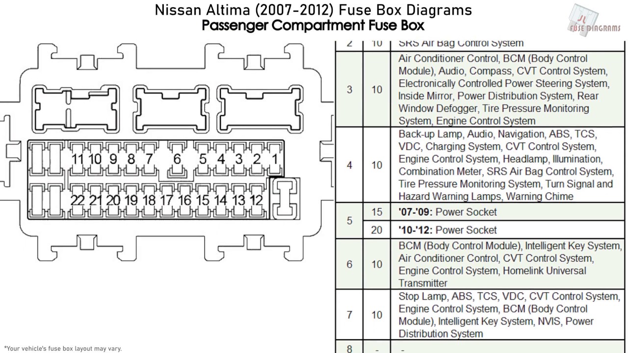
The 2011 Nissan Altima, like most modern vehicles, has multiple fuse boxes. The primary one is typically located inside the cabin, often under the dashboard on the driver's side. There's usually a second fuse box located in the engine compartment, near the battery. Each fuse box contains an array of fuses and relays. It's important to consult the diagram specific to *your* trim level, as fuse allocations can vary. Here's a breakdown of the main components:
- Fuses: These are the sacrificial components designed to protect electrical circuits from overcurrent. They contain a thin wire or strip that melts and breaks the circuit if the current exceeds a safe level. Fuses are typically rated in Amperes (A), indicating the amount of current they can handle before blowing. Common ratings include 5A, 7.5A, 10A, 15A, 20A, 25A, and 30A.
- Relays: Relays are electromechanical switches that allow a low-current circuit to control a high-current circuit. They are used to switch on and off components that draw a lot of power, such as headlights, the starter motor, and the fuel pump. The diagram will indicate the function of each relay.
- Fuse Puller: A small plastic tool included in many fuse boxes, used to safely remove and replace fuses without damaging them or yourself.
- Fuse Box Cover: The cover provides protection for the fuses and relays and often contains a simplified diagram of the fuse layout. However, always refer to the complete diagram for accurate information.
Understanding the Symbols on the Diagram
The fuse box diagram uses symbols to represent various electrical components and connections. Understanding these symbols is crucial for interpreting the diagram correctly.
- Lines: Lines represent wires or electrical conductors. Thicker lines may indicate higher current capacity.
- Colors: Wire colors are often indicated on the diagram using abbreviations (e.g., BLU for Blue, RED for Red, BLK for Black). These colors help you trace wires in the vehicle.
- Icons: Icons represent the components powered by the fuses. Common icons include headlights, taillights, radio, power windows, wipers, and the engine control unit (ECU). The ECU, also known as the engine control module (ECM) or powertrain control module (PCM), is the car's main computer.
- Fuse Ratings: Each fuse location is labeled with its amperage rating (e.g., 15A). This indicates the maximum current that the fuse can handle.
- Ground Symbols: Indicate a connection to the vehicle's chassis, which serves as a common ground for the electrical system.
- Relay Symbols: Represent the relay itself. The diagram may also show the relay's coil and contact circuits.
How It Works: Following the Circuit
Understanding how electricity flows through a circuit is fundamental. Power originates from the battery and is distributed throughout the vehicle via wires. Each circuit is protected by a fuse. If a component malfunctions and draws excessive current, the fuse blows, interrupting the circuit and preventing damage to the wiring and other components. Think of it like this: electricity flows from the battery, through the fuse, to the component, and then back to the ground. The fuse is the weakest link, designed to break before anything else.
Using the diagram, you can trace the circuit for a specific component. For example, if your headlights aren't working, you can locate the headlight fuse on the diagram, identify its amperage rating, and then physically locate the fuse in the fuse box. If the fuse is blown, replacing it should restore power to the headlights.
Real-World Use: Basic Troubleshooting Tips
Here are some basic troubleshooting tips using the fuse box diagram:
- Identify the Problem: Determine which component is malfunctioning.
- Consult the Diagram: Locate the fuse or relay associated with the malfunctioning component on the fuse box diagram.
- Inspect the Fuse: Visually inspect the fuse. A blown fuse will typically have a broken filament. You can also use a multimeter to test the fuse for continuity. Set your multimeter to the continuity setting (often indicated by a diode symbol or a sound). Place the probes on each end of the fuse. If the multimeter beeps or shows a reading of close to zero, the fuse is good. If it shows no continuity (an open circuit), the fuse is blown.
- Replace the Fuse: Replace the blown fuse with a new fuse of the same amperage rating. Never use a fuse with a higher rating, as this could damage the wiring.
- Test the Component: After replacing the fuse, test the component to see if it is now working.
- If the Fuse Blows Again: If the new fuse blows immediately or shortly after being replaced, there is likely a short circuit in the wiring or a faulty component. Further diagnosis is required. This might involve tracing the wires, checking for damaged insulation, and testing the component itself.
Safety Considerations
Working with electrical systems can be dangerous. Here are some important safety precautions:
- Disconnect the Battery: Before working on any electrical system, disconnect the negative terminal of the battery to prevent accidental shorts.
- Use Proper Tools: Use insulated tools to avoid electric shock.
- Never Replace a Fuse with a Higher Rating: This can overload the circuit and cause a fire.
- Identify High-Risk Components: The diagram can help identify circuits related to critical systems like the fuel pump, airbags, and ABS. Be extremely cautious when working on these systems and consult a qualified mechanic if you're not comfortable. The airbag system, in particular, is extremely sensitive and can deploy unexpectedly if mishandled. Similarly, the fuel pump circuit should be handled with care to avoid fuel leaks and potential fire hazards.
- Work in a Well-Lit Area: Good lighting is essential for seeing clearly and avoiding mistakes.
- Consult a Professional: If you are unsure about any aspect of the electrical system, consult a qualified mechanic.
By understanding the 2011 Nissan Altima fuse box diagram and following these safety precautions, you can confidently tackle many electrical repairs and modifications on your own, saving time and money while gaining a deeper understanding of your vehicle.
We have the 2011 Nissan Altima fuse box diagram available for download. It provides a detailed layout of all the fuses and relays in both the interior and engine compartment fuse boxes.