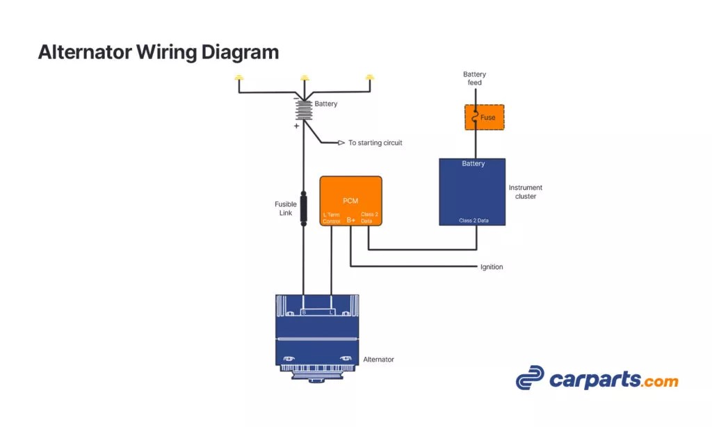
2011 Nissan Maxima Alternator Wiring Diagram
Alright, let's dive into the 2011 Nissan Maxima alternator wiring diagram. This isn't just some piece of paper; it's your roadmap to understanding, diagnosing, and potentially repairing charging system issues on your Maxima. Whether you're dealing with a dead battery, dimming headlights, or just want to understand how your car's electrical system ticks, knowing how to read and interpret this diagram is crucial.
Purpose of the Diagram
This diagram serves several critical purposes:
- Troubleshooting: When you're experiencing electrical problems related to the charging system, the diagram helps you pinpoint the exact components and wiring that might be at fault.
- Repair: Replacing a faulty alternator or repairing damaged wiring becomes much easier and safer when you have a clear picture of how everything connects.
- Modification: If you're planning to add aftermarket accessories that draw power from the charging system (like a high-powered sound system or auxiliary lights), the diagram helps you understand the system's capacity and how to safely integrate new components.
- Understanding: It gives you a solid grasp of how the alternator, battery, and other electrical components interact, increasing your overall automotive knowledge.
Key Specs and Main Parts
Before we dissect the wiring, let's cover the core components involved in the 2011 Maxima's charging system:
Alternator
The heart of the charging system. The 2011 Maxima uses a 12V alternator, and its amperage output varies depending on the specific trim level and engine configuration. Typically, it's somewhere in the range of 130-150 amps. Its primary job is to convert mechanical energy (from the engine) into electrical energy, which then charges the battery and powers the car's electrical components.
Battery
A 12V lead-acid battery stores electrical energy and provides power to start the engine and operate electrical components when the engine is off. A healthy battery is critical for proper alternator function.
Voltage Regulator
This is often integrated within the alternator on modern vehicles like the Maxima. The voltage regulator maintains a consistent voltage output (around 13.5-14.5V) from the alternator, preventing overcharging and damage to the battery and other electrical components. Think of it as the alternator's governor.
Fusible Link/Main Fuse
A high-amperage fuse or fusible link protects the entire charging system from overloads and short circuits. This is typically located near the battery and is a crucial safety device.
Wiring Harness
This bundle of wires connects all the components together. These wires are color-coded, as shown on the wiring diagram, and are essential for the flow of electricity.
Charging System Indicator (Warning Light)
Located on the instrument cluster, this light illuminates when the charging system isn't functioning correctly (e.g., low voltage output from the alternator). Don't ignore this light!
Understanding Wiring Diagram Symbols
Decoding the wiring diagram is essential. Here's a breakdown of common symbols:
- Solid Lines: Represent wires connecting different components. The thickness of the line doesn't usually indicate wire gauge, but always refer to the legend on the diagram for specifics.
- Dashed Lines: Often indicate wires within a harness or wires that are grounded to the chassis.
- Color Codes: Each wire is assigned a color code (e.g., "B" for Black, "R" for Red, "W" for White, "L" for Blue). These codes are crucial for identifying the correct wires when working on the car. You'll usually find these codes abbreviated next to the lines.
- Ground Symbol: Usually looks like three horizontal lines stacked on top of each other, decreasing in size. This indicates a connection to the vehicle's chassis, which acts as the ground for the electrical system.
- Fuse Symbol: Typically a zigzag line enclosed in a rectangle. Indicates a fuse location.
- Relay Symbol: Often a rectangle with internal coils and switch contacts. Relays are electrically operated switches that control high-current circuits using a low-current signal.
- Component Symbols: Each component (alternator, battery, etc.) has a specific symbol that represents it. The diagram usually includes a legend that explains what each symbol means.
- Connectors: Represented by various shapes (circles, squares, or rectangles). The diagram will often indicate the connector's pin numbers and the corresponding wire colors.
Important: Always refer to the specific legend on the 2011 Nissan Maxima alternator wiring diagram you're using. Symbols and conventions can vary slightly between different diagrams and manufacturers.
How the Charging System Works
Here's the basic flow of electricity in the charging system:
- When the engine starts, the crankshaft drives the alternator's pulley via the serpentine belt.
- The alternator begins to rotate, and its internal components (rotor and stator) generate AC (alternating current) electricity.
- The AC electricity is then converted to DC (direct current) by the alternator's rectifier.
- The voltage regulator monitors the battery's voltage and adjusts the alternator's output accordingly.
- The DC electricity flows from the alternator to the battery, charging it and providing power to the car's electrical components (lights, radio, sensors, etc.).
- Any excess electricity is stored in the battery for later use.
Real-World Use & Basic Troubleshooting
Let's say your 2011 Maxima's battery keeps dying. Here's how the wiring diagram can help:
- Check the Charging System Indicator: If the light is on, it indicates a problem with the charging system.
- Visual Inspection: Examine the alternator, battery terminals, and wiring harness for any signs of damage, corrosion, or loose connections. Use the wiring diagram to locate the specific wires and connectors involved.
- Voltage Test: Use a multimeter to measure the voltage at the battery terminals with the engine running. A healthy charging system should produce around 13.5-14.5 volts. If the voltage is significantly lower, the alternator might be faulty, or there could be a problem with the wiring.
- Continuity Test: Use a multimeter to check the continuity of the wiring between the alternator and the battery. A break in the wiring can prevent the battery from charging. Use the diagram to identify the specific wires to test.
- Check the Fuses/Fusible Links: Use the diagram to locate and inspect the main fuse or fusible link in the charging system. A blown fuse indicates an overload or short circuit.
Example: You suspect a bad connection between the alternator and the battery. The diagram shows a red wire (R) connecting the alternator's output terminal to the positive terminal of the battery. You use your multimeter to check the voltage drop across this wire. A significant voltage drop indicates a bad connection or damaged wire.
Safety First!
Warning: Working with electrical systems can be dangerous. Always disconnect the negative battery terminal before working on any electrical components. This prevents accidental short circuits and electrical shocks. The alternator output wire carries high current and can cause severe burns or electrical shock if shorted to ground.
Specifically, be cautious around these components:
- Alternator Output Terminal: This terminal carries high voltage and current. Avoid touching it while the engine is running or the battery is connected.
- Battery Terminals: Batteries contain corrosive acid and can produce explosive gases. Wear safety glasses and gloves when working around batteries.
- Wiring Harness: Inspect the wiring harness carefully for any signs of damage or wear. Damaged wiring can cause short circuits and fires.
Working on your car's electrical system can be rewarding, but always prioritize safety. If you're not comfortable working with electrical components, it's best to consult a qualified mechanic.
Remember, having the correct wiring diagram is key. We have the 2011 Nissan Maxima Alternator Wiring Diagram available for download. This detailed diagram will provide all the specific information you need to troubleshoot and repair your vehicle's charging system. Good luck!