2011 Nissan Murano Fuse Box Diagram
The 2011 Nissan Murano, a crossover known for its blend of style and practicality, relies heavily on its electrical system for everything from starting the engine to powering the infotainment center. At the heart of this system are the fuse boxes. Understanding the 2011 Nissan Murano fuse box diagram is invaluable for any owner looking to perform basic maintenance, troubleshoot electrical problems, or even customize their vehicle with aftermarket accessories.
Purpose of the Fuse Box Diagram
Why bother understanding the fuse box diagram? Simply put, it's the roadmap to your Murano's electrical system. It's crucial for several reasons:
- Troubleshooting Electrical Issues: When a component stops working, the first thing you should check is the fuse. The diagram tells you which fuse corresponds to which circuit.
- Preventing Further Damage: A blown fuse indicates an overload or a short circuit. Replacing it with the wrong amperage fuse can cause severe damage to the affected component and wiring.
- Safe Customization: If you're adding aftermarket electronics, you need to tap into existing circuits safely. The diagram helps you identify suitable points to draw power from and select the appropriate fuse rating for the new device.
- Learning Vehicle Systems: Studying the diagram provides a deeper understanding of how different systems within your Murano are interconnected and powered.
Key Specs and Main Parts
The 2011 Murano typically has two main fuse boxes:
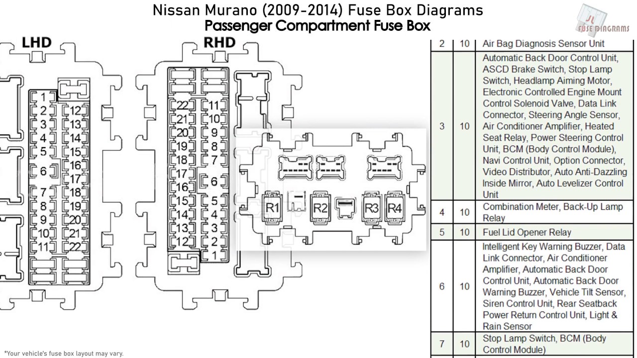
- Interior Fuse Box: Located inside the cabin, often under the dashboard (typically on the driver's side or behind the glove box). This box primarily houses fuses for interior components like the radio, climate control, interior lights, power windows, and the 12V accessory socket.
- Engine Compartment Fuse Box: Situated under the hood, near the engine bay. This box contains fuses for critical engine components, headlights, the anti-lock braking system (ABS), and the electronic power steering (EPS). Some larger fuses in the engine compartment are also called fusible links, which are designed to handle very high current loads.
Key specs to note about fuses include:
- Amperage Rating: Measured in amps (A), this indicates the maximum current the fuse can handle before blowing. Common ratings include 5A, 7.5A, 10A, 15A, 20A, 25A, and 30A. Using a fuse with a higher amperage rating than specified is extremely dangerous and can cause a fire.
- Fuse Type: The 2011 Murano generally uses blade-type fuses, also known as spade fuses. These come in different sizes, such as mini, standard, and maxi. It’s essential to use the correct type of fuse when replacing one.
- Fusible Links: High-current protection devices, often used for circuits like the alternator or starter motor. They resemble short wires with a protective insulation around them.
Understanding the Fuse Box Diagram Symbols
The fuse box diagram isn't just a collection of numbers and letters. It utilizes standardized symbols and conventions to convey information clearly.
- Lines: Solid lines typically represent the electrical circuits. The thicker the line, the higher the current capacity of the circuit.
- Colors: Different colored wires represent different circuits and purposes. While the diagram itself may not be in color, knowing the wire colors within your Murano's wiring harness is beneficial. Consult the vehicle's service manual for wire color codes.
- Icons: Icons represent the component that the fuse protects. Common icons include:
- Headlight: Indicates a fuse protecting the headlight circuit.
- Radio: Indicates a fuse protecting the radio/audio system circuit.
- Fan: Indicates a fuse protecting a cooling fan circuit.
- Cigar Lighter/Accessory Socket: Indicates a fuse protecting the 12V power outlet.
- Numbers and Letters: Each fuse location is typically labeled with a number or a combination of letters and numbers. This corresponds to the same designation on the fuse box diagram.
- Abbreviations: You'll encounter abbreviations such as "IGN" (ignition), "ACC" (accessory), "PWR" (power), and "ECU" (engine control unit).
How It Works: The Electrical Circuit
To truly understand the diagram, you need to grasp the basic concept of an electrical circuit. Electricity flows from the battery, through the wiring, to the component (e.g., a headlight), and back to the battery, completing the circuit.
The fuse is placed in this circuit as a sacrificial element. If the current flow exceeds the fuse's amperage rating (due to a short circuit or an overload), the fuse's internal filament melts (blows), breaking the circuit and stopping the flow of electricity. This prevents damage to the component and potentially a fire.
The fuse box diagram shows you which fuse is connected to which part of the circuit. By identifying the correct fuse, you can isolate the problem to a specific area.
Real-World Use: Basic Troubleshooting Tips
Here's how to use the fuse box diagram to troubleshoot common electrical problems:
- Identify the Symptom: What's not working? Be specific. For example, "The driver's side power window isn't working."
- Consult the Diagram: Locate the fuse box diagram (usually found in your owner's manual or online – and available for download from us!). Find the fuse labeled for the driver's side power window.
- Locate the Fuse: Open the appropriate fuse box and find the fuse corresponding to the label on the diagram.
- Inspect the Fuse: Remove the fuse using a fuse puller (a small plastic tool designed for this purpose). Look closely at the fuse's filament. If it's broken, the fuse is blown.
- Replace the Fuse: Replace the blown fuse with a new fuse of the exact same amperage rating and type.
- Test the Component: Turn on the ignition and test the power window. If it works, the problem is solved. If the new fuse blows immediately, there's a short circuit in the wiring or the power window motor itself. This requires further investigation and potentially professional help.
Example: The radio isn't working. You consult the diagram, find the fuse labeled "Radio," and discover it's a 15A fuse. You locate the 15A fuse in the interior fuse box, remove it, and see the filament is broken. You replace it with a new 15A fuse, and the radio starts working again.
Safety Considerations
Working with electrical systems can be dangerous. Here are some important safety precautions:
- Disconnect the Battery: Before working on any electrical component, disconnect the negative terminal of the battery. This prevents accidental short circuits and electrical shocks.
- Use the Right Tools: Use a fuse puller to remove fuses. Avoid using metal objects, as they can cause short circuits.
- Never Bypass a Fuse: Never insert a wire or any other object in place of a fuse. This can cause a fire.
- Replace with the Correct Amperage: Always replace a blown fuse with a fuse of the exact same amperage rating. Using a higher amperage fuse can overload the circuit and cause a fire.
- Beware of High-Voltage Components: Some components, such as the ignition system, store high voltage even after the engine is turned off. Avoid touching these components unless you are properly trained.
- Consult a Professional: If you're uncomfortable working with electrical systems, consult a qualified mechanic.
Especially risky components to avoid are the SRS (Supplemental Restraint System) components, such as airbags. Tampering with these systems can lead to accidental deployment, causing serious injury.
Understanding the 2011 Nissan Murano fuse box diagram empowers you to diagnose and resolve minor electrical issues, saving you time and money. However, remember to always prioritize safety and consult a professional for complex problems.
To help you further, we have the complete 2011 Nissan Murano Fuse Box Diagram available for download. This detailed diagram will provide you with the specific locations and amperage ratings for all the fuses in your vehicle.