2011 Nissan Murano Serpentine Belt Diagram
Maintaining the serpentine belt on your 2011 Nissan Murano is crucial for the proper functioning of various engine components. A worn or broken serpentine belt can lead to a host of problems, including a loss of power steering, air conditioning, and even engine overheating. This article provides a detailed technical guide to understanding the serpentine belt diagram for your Murano, enabling you to perform preventative maintenance, diagnose issues, and potentially save on costly repairs. We'll break down the diagram's key elements, function, and practical application.
Purpose of the Serpentine Belt Diagram
The serpentine belt diagram is essentially a roadmap for the belt's path around the various pulleys driven by the engine. Understanding this diagram is invaluable for several reasons:
- Belt Replacement: It's critical when replacing a worn or damaged belt to ensure the new belt is routed correctly. An incorrectly routed belt will not function properly and can quickly be damaged.
- Troubleshooting: The diagram helps diagnose potential issues. For instance, squealing noises can often be traced to a misaligned or worn belt, and the diagram helps you identify which component might be contributing to the problem.
- Maintenance: Understanding the layout allows for easier inspection of the belt and pulleys for wear, cracks, or damage. Regular inspection is key to preventative maintenance.
- Learning Vehicle Systems: Studying the diagram provides a better understanding of how the various engine accessories are driven, which is helpful for broader mechanical comprehension.
Key Specs and Main Parts in the 2011 Murano's Serpentine Belt System
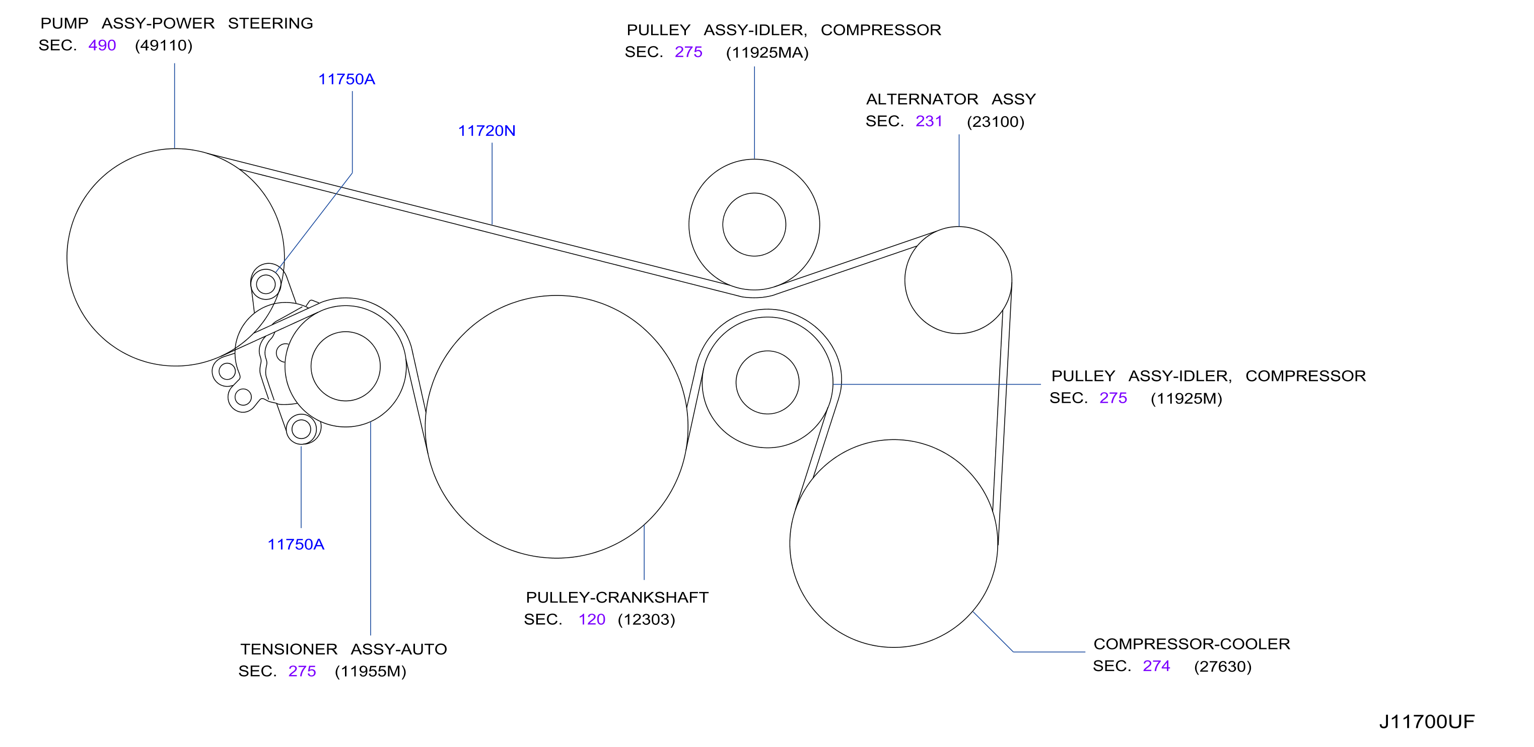
The 2011 Nissan Murano uses a single, long, multi-ribbed belt – the serpentine belt – to drive several key engine accessories. The specific engine in your Murano (typically a 3.5L V6 VQ35DE) dictates the exact length and configuration of the belt, but the core components remain the same. Knowing these components and their function is essential to interpreting the diagram effectively.
- Crankshaft Pulley (or Harmonic Balancer): This is the driving pulley, connected directly to the engine's crankshaft. It's the source of power for the entire serpentine belt system.
- Alternator Pulley: The alternator generates electrical power for the vehicle's systems and charges the battery. The serpentine belt drives it.
- Power Steering Pump Pulley: This pulley drives the power steering pump, which provides hydraulic assistance to the steering system.
- Air Conditioning Compressor Pulley: This pulley drives the A/C compressor, responsible for cooling the cabin.
- Idler Pulley(s): These are smooth, non-driven pulleys that guide the belt and maintain proper tension in the system. They are crucial for ensuring the belt has adequate wrap around the driven pulleys.
- Tensioner Pulley: This pulley is spring-loaded and automatically maintains the correct tension on the serpentine belt. It prevents slippage and ensures optimal performance of all driven accessories. The tensioner assembly includes a pulley and a spring-loaded arm.
The serpentine belt itself is a crucial component. It's typically made of reinforced rubber and has multiple V-shaped ribs running along its length to maximize grip on the pulleys.
Understanding Diagram Symbols and Conventions
Serpentine belt diagrams utilize a standard set of symbols and conventions to convey information concisely:
- Solid Lines: Represent the path of the serpentine belt. The thickness of the line typically doesn't have any specific meaning, but it clearly indicates the belt's route.
- Circles: Represent pulleys. The size of the circle doesn't necessarily reflect the actual size of the pulley, but they are generally proportional.
- Arrows: Indicate the direction of rotation for each pulley. This is crucial for understanding how the belt is routed and how the accessories are driven.
- Component Labels: Each pulley will be labeled with an abbreviation identifying the component it drives (e.g., ALT for Alternator, P/S for Power Steering, A/C for Air Conditioning, CRANK for Crankshaft).
- Tensioner Indicator: The tensioner pulley is often depicted with a symbol indicating its spring-loaded action. This might be a small arrow showing the direction of tension application, or a stylized representation of the spring itself.
- Rough Side vs. Smooth Side: Diagrams may differentiate between the grooved (ribbed) side of the belt that contacts the driven pulleys, and the smooth back side of the belt that contacts the idler pulley. This is often indicated by showing a thicker line representing the grooved side.
Modern diagrams may also use color coding, though this is less common on simpler diagrams. If present, the legend will explain the meaning of each color.
How the Serpentine Belt System Works
The engine's crankshaft, via the crankshaft pulley, provides the rotational force that drives the entire serpentine belt system. As the crankshaft rotates, it turns the serpentine belt, which in turn spins all the other pulleys connected to it. The tensioner pulley maintains the necessary tension on the belt to prevent slippage and ensure efficient power transfer to each accessory.
The routing of the belt is designed to maximize the *angle of wrap* around each pulley. Angle of wrap refers to the amount of the pulley's circumference that the belt actually contacts. A greater angle of wrap translates to better grip and reduced slippage, especially for components that require significant power, such as the alternator and A/C compressor. Idler pulleys are strategically placed to optimize these wrap angles.
The tensioner pulley is critical for proper operation. As the belt stretches over time, or as temperature changes affect the belt's length, the tensioner automatically adjusts to maintain the correct tension. A failing tensioner can cause belt slippage, noise, and premature belt wear.
Real-World Use and Basic Troubleshooting
Here are some practical tips for using the serpentine belt diagram for troubleshooting:
- Squealing Noise: A squealing noise often indicates a slipping belt. Use the diagram to inspect the belt for cracks, glazing (a shiny surface), or damage. Also, check the tensioner pulley for proper operation. A worn or seized tensioner can cause the belt to slip.
- Visual Inspection: Regularly inspect the belt for wear and tear. Look for cracks, fraying, missing ribs, or signs of oil contamination. Any of these conditions warrant belt replacement.
- Component Failure: If an accessory, such as the alternator or power steering pump, is not functioning correctly, the diagram helps you isolate the problem. If the belt is properly routed and in good condition, the issue likely lies within the accessory itself.
- Belt Routing After Replacement: *Always* refer to the diagram when replacing the serpentine belt. Incorrect routing is a common mistake that can lead to immediate damage to the belt and/or the accessories. Take a picture of the original belt routing *before* removing it as a backup.
- Tensioner Check: With the engine off, visually inspect the tensioner pulley. The indicator marks on the tensioner body show the acceptable operating range. If the tensioner arm is extended beyond these marks, the belt is likely stretched and needs replacement.
Safety Considerations
Working on the serpentine belt system involves inherent risks:
- Rotating Parts: The serpentine belt and pulleys are extremely dangerous when the engine is running. Never attempt to diagnose or work on the system with the engine running unless absolutely necessary and you are qualified to do so, and understand the risks.
- Hot Components: The engine and exhaust system can be very hot, even after the engine has been off for a while. Allow the engine to cool completely before working on the system to avoid burns.
- Spring Tension: The tensioner pulley is spring-loaded and can snap back forcefully if released improperly. Use the correct tools to relieve the tension on the belt safely. Usually, a wrench is used to rotate the tensioner arm against the spring pressure, allowing the belt to be removed or installed.
- Battery Disconnect: It is always a good practice to disconnect the negative battery terminal before working on any electrical or mechanical components of a vehicle.
Always wear safety glasses and gloves when working on the serpentine belt system. Use the correct tools and follow the manufacturer's instructions carefully.
By understanding the serpentine belt diagram and following safe work practices, you can effectively maintain and troubleshoot this critical system on your 2011 Nissan Murano, helping to ensure reliable performance and prevent costly repairs.
We have a downloadable PDF file of the 2011 Nissan Murano Serpentine Belt Diagram available for your use. This diagram provides a clear visual aid for belt routing and component identification. Contact us to receive the file.