2012 Chevy Traverse Fuse Box Diagram
For the intermediate car owner, modder, or DIY mechanic, understanding your vehicle's electrical system is crucial. The fuse box is the central nervous system of that system, protecting delicate components from overcurrent and potential damage. Specifically, knowing the 2012 Chevy Traverse fuse box diagram can be invaluable for troubleshooting electrical issues, performing modifications, or simply gaining a deeper understanding of your vehicle. This article will serve as a comprehensive guide to interpreting and utilizing this essential resource.
Purpose of the 2012 Chevy Traverse Fuse Box Diagram
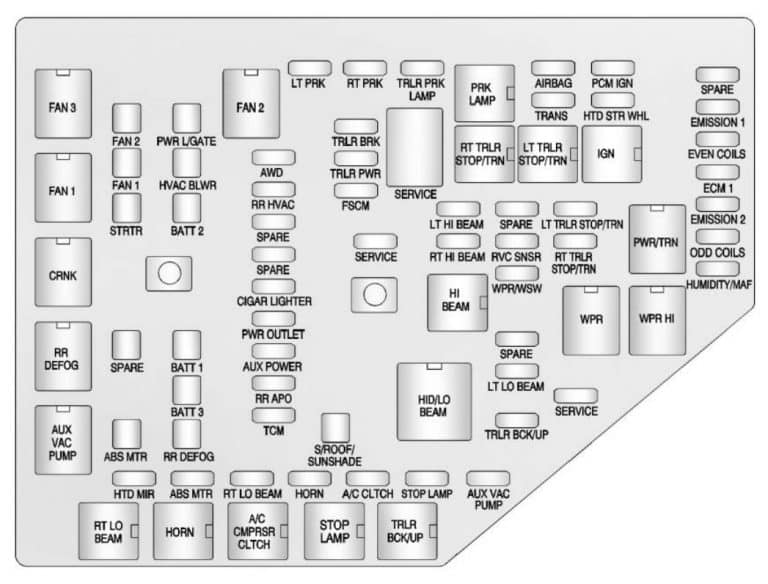
The primary purpose of the fuse box diagram is to provide a visual representation of the location and function of each fuse and relay within your 2012 Chevy Traverse's electrical system. This diagram is essential for:
- Troubleshooting Electrical Problems: Identifying a blown fuse is the first step in diagnosing many electrical malfunctions. The diagram allows you to quickly locate the fuse associated with the affected component.
- Performing Repairs: When replacing a blown fuse, you need to ensure you are using the correct amperage rating. The diagram specifies the amperage for each fuse.
- Adding Aftermarket Accessories: When installing aftermarket accessories like lights, stereos, or alarms, you may need to tap into the vehicle's electrical system. The diagram helps you identify suitable power sources and protect the new circuit.
- Understanding the Electrical System: Even if you're not actively troubleshooting, studying the diagram can provide a better understanding of how the various electrical components in your Traverse are connected and protected.
Key Specs and Main Parts
The 2012 Chevy Traverse typically has two main fuse box locations:
- Underhood Fuse Box: Located in the engine compartment, this fuse box houses fuses and relays for critical systems such as the engine control module (ECM), transmission control module (TCM), ABS, headlights, and other essential functions. This is usually the larger of the two fuse boxes.
- Instrument Panel Fuse Box: Located inside the cabin, often under the dashboard on the driver's side or passenger's side, this fuse box contains fuses and relays for interior components such as the radio, power windows, power locks, and interior lighting.
Key specs to pay attention to include:
- Fuse Amperage Rating: This is the maximum current (measured in Amperes or Amps) that the fuse can handle before blowing. It is usually printed on the fuse itself. Common values include 5A, 7.5A, 10A, 15A, 20A, 25A, 30A, and 40A. Using a fuse with a higher amperage rating than specified can damage the circuit and connected components.
- Fuse Type: The 2012 Traverse typically uses blade-type fuses, also known as spade fuses. There are different sizes of blade fuses, including regular, mini, and low-profile mini.
- Relay Type: Relays are electromechanical switches that allow a low-current circuit to control a high-current circuit. They come in various configurations, such as single-pole single-throw (SPST) and single-pole double-throw (SPDT).
Symbols: Lines, Colors, and Icons
Understanding the symbols used in the fuse box diagram is crucial for proper interpretation. Common symbols include:
- Lines: Represent wires connecting different components. Thicker lines may indicate higher current capacity.
- Colors: Different colored wires are used to differentiate circuits and signal functions. The diagram may include a color code legend. Common colors include red (power), black (ground), and various other colors for specific signals.
- Icons: Icons represent the components protected by the fuses. Common icons include:
- A headlight icon for headlight fuses.
- A radio icon for the radio fuse.
- A window icon for power window fuses.
- An engine icon for engine-related fuses.
- Etc.
Pay close attention to the legend provided with the diagram. This legend will explain the meaning of each symbol and color used.
How It Works: Fuses and Relays in Action
Fuses: A fuse is a sacrificial device designed to protect an electrical circuit from overcurrent. It contains a thin wire that melts and breaks the circuit if the current exceeds its rated amperage. This prevents damage to more expensive components like the ECM or other sensitive electronics. Think of it as a safety valve for electricity.
Relays: A relay is an electromechanical switch that allows a low-current circuit (the control circuit) to control a high-current circuit (the load circuit). When current flows through the control circuit, it energizes an electromagnet that pulls a switch, closing the load circuit and allowing current to flow to the component being controlled. Relays are used to control high-current devices like headlights, starter motors, and air conditioning compressors, where directly switching the high current with a manual switch would be impractical or dangerous.
The fuse box diagram shows the location of each fuse and relay, along with its function and amperage rating. By consulting the diagram, you can quickly identify the fuse or relay associated with a particular component and determine if it is the source of a problem.
Real-World Use: Basic Troubleshooting Tips
Here are some basic troubleshooting tips using the fuse box diagram:
- Identify the Problem: Determine which electrical component is not working correctly (e.g., headlights, radio, power windows).
- Consult the Diagram: Use the fuse box diagram to locate the fuse associated with the malfunctioning component.
- Inspect the Fuse: Remove the fuse and visually inspect it. A blown fuse will have a broken filament or a blackened appearance.
- Replace the Fuse: Replace the blown fuse with a new fuse of the exact same amperage rating. Using a higher amperage fuse can damage the circuit.
- Test the Component: After replacing the fuse, test the component to see if it is now working correctly.
- If the Fuse Blows Again: If the new fuse blows immediately or shortly after being replaced, there is likely a short circuit or other underlying problem in the circuit. Further diagnosis is required to identify and repair the fault. This may involve checking wiring for damage or testing components for shorts.
- Check Relays: If the component still doesn't work after replacing the fuse, the relay may be faulty. You can test the relay by swapping it with a known good relay or by using a multimeter to check its continuity.
Safety: Highlight Risky Components
Working with automotive electrical systems can be dangerous. Here are some safety precautions to keep in mind:
- Disconnect the Battery: Always disconnect the negative battery cable before working on the electrical system. This will prevent accidental shorts and electrical shocks.
- Use Proper Tools: Use insulated tools designed for automotive electrical work.
- Never Bypass a Fuse: Bypassing a fuse with a wire or other conductive material is extremely dangerous and can cause a fire.
- Be Careful Around Airbags: Airbags are controlled by the electrical system and can deploy unexpectedly if triggered. Consult the vehicle's service manual for instructions on disabling the airbag system before working near airbag components.
- High Voltage Systems: Be aware that some components, such as the ignition system, operate at high voltage. Avoid contact with these components when the engine is running.
Working on the fuel pump circuit can be dangerous due to the risk of fuel spillage and fire. Always take extra precautions when working on this circuit.
By understanding the 2012 Chevy Traverse fuse box diagram, you can confidently diagnose and resolve many common electrical issues. Remember to always prioritize safety and consult the vehicle's service manual for specific instructions and warnings.
To further assist you, we have a high-resolution PDF version of the 2012 Chevy Traverse fuse box diagram available for download. This detailed diagram will provide you with all the information you need to effectively troubleshoot and repair your vehicle's electrical system. Contact us to request access to the file.