2012 Chrysler Town And Country Fuse Box Diagram
Hey there, fellow gearheads! Let's dive into the 2012 Chrysler Town and Country fuse box diagram. For those of you who like to get your hands dirty with car repairs, upgrades, or even just understanding your vehicle's electrical system, knowing how to read and interpret this diagram is absolutely crucial.
Why the Fuse Box Diagram Matters
Think of the fuse box as the central nervous system of your Town and Country's electrical system. It's the protector, the guardian against overloads and shorts. Without a clear understanding of its layout – which is precisely what the fuse box diagram provides – you're basically working in the dark when electrical problems arise. Specifically, this diagram matters for:
- Troubleshooting Electrical Issues: Diagnosing why your power windows stopped working or why your tail lights are out becomes far simpler.
- Replacing Blown Fuses: Identifying the correct replacement fuse is crucial to avoid further damage.
- Adding Aftermarket Accessories: Safely tapping into the electrical system for adding accessories like a dashcam or aftermarket lights requires knowing which circuits are available and properly protected.
- Learning Vehicle Electrical Systems: Even if you don't plan on doing repairs yourself, understanding the fuse box is a great way to learn the basics of how your van's electrical system is designed.
- Preventing Costly Repairs: Catching minor electrical issues early, thanks to understanding your fuse box, can prevent bigger, more expensive problems down the road.
Key Specs and Main Parts of the 2012 Town and Country Fuse Box
The 2012 Chrysler Town and Country typically has two primary fuse box locations:
- The Interior Fuse Box (also known as the Junction Block): Usually located inside the cabin, often on the driver's side, under the dashboard or behind a panel near the steering wheel. This box primarily houses fuses related to interior accessories like lights, the radio, power windows, and the climate control system.
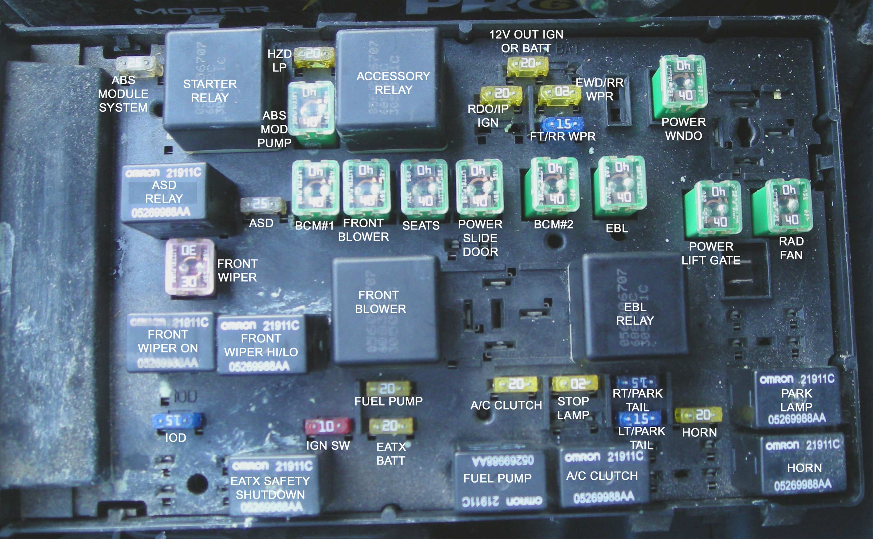
- The Power Distribution Center (PDC) or Under-Hood Fuse Box: Found under the hood, this box manages the higher-current circuits related to the engine, transmission, and other essential systems like the ABS (Anti-lock Braking System) and cooling fan.
Key specs include:
- Voltage: The entire system operates at 12V DC (Direct Current).
- Fuse Types: Mini blade fuses are commonly used, with amperage ratings ranging from 5A (Amperes) to 30A or higher depending on the circuit. Always replace a fuse with one of the same amperage rating.
- Relays: The PDC also contains relays, which are electromechanical switches that control high-current circuits using a low-current signal. Examples include the fuel pump relay, starter relay, and horn relay. A relay is basically an electrically operated switch.
Decoding the Symbols: Lines, Colors, and Icons
The fuse box diagram isn't just a random collection of numbers; it's a schematic with a standardized language. Understanding the symbols is key to proper interpretation.
- Lines: Solid lines represent wired connections. Thicker lines often indicate higher current-carrying capacity. Dashed lines may represent connections that are optional or present only on specific trims.
- Colors: Wire colors are often indicated on the diagram (e.g., RD for Red, BLK for Black, YEL for Yellow). These colors help you trace wires in the physical vehicle.
- Icons: This is where it gets interesting. Icons represent the devices that the fuses and relays protect. Common icons include:
- Light Bulb: Indicates a lighting circuit (headlights, taillights, interior lights).
- Fan: Indicates a motor, often the blower motor or cooling fan.
- Radio: Represents the audio system.
- Window: Indicates a power window circuit.
- Engine: Represents engine control circuits.
- Horn: Represents the horn circuit.
- Battery Symbol: Represents a direct connection to the vehicle's battery.
- Numbers: Each fuse and relay is labeled with a number or alphanumeric code. This code corresponds to a listing in the diagram that describes the circuit it protects and its amperage rating.
A critical aspect of the diagram is its representation of circuit protection. It shows how each electrical component is connected to the battery through a specific fuse or relay. This ensures that if there's a fault, the fuse blows (or the relay trips), preventing damage to the component and potentially preventing a fire.
How It Works: From Battery to Component
Imagine a simple circuit: the cigarette lighter. Power flows from the battery, through a fuse in the interior fuse box (as designated by the diagram), and then to the cigarette lighter socket. The fuse is sized to protect the wiring and the lighter socket itself. If you plug in a device that draws too much current, the fuse will blow, breaking the circuit and preventing overheating or damage.
The diagram shows this flow. It indicates the wire colors, the fuse location, the amperage rating of the fuse, and the icon for the cigarette lighter. By following the lines on the diagram, you can trace the entire circuit from the battery to the component.
Real-World Use: Basic Troubleshooting Tips
Okay, so you've got the diagram. Now what? Here are a few troubleshooting scenarios:
- Power Windows Not Working: Check the fuse listed for the power windows in the interior fuse box diagram. If the fuse is blown, replace it with one of the correct amperage. If it blows again immediately, there's likely a short in the wiring or a faulty window motor.
- Headlights Not Working: Consult the under-hood fuse box diagram. There might be separate fuses for the left and right headlights. Check both. If both are good, then the problem could be with the headlight switch, the bulbs themselves, or the wiring.
- Radio Not Turning On: Locate the radio fuse in the interior fuse box diagram. If the fuse is good, check the wiring connections at the back of the radio. The problem could also be a faulty radio unit.
Important Tip: Before replacing a blown fuse, try to determine the cause. Repeatedly blowing fuses is a sign of a bigger problem, such as a short circuit.
Safety First: Risky Components and Practices
Working with automotive electrical systems can be dangerous. Always prioritize safety:
- Disconnect the Battery: Before working on any electrical components, disconnect the negative terminal of the battery. This prevents accidental shorts and electrical shocks.
- Avoid Water: Never work on electrical systems in wet conditions.
- Use Proper Tools: Use insulated tools designed for automotive electrical work.
- Never Bypass a Fuse: Do not replace a fuse with a higher amperage fuse or a piece of wire. This can overload the circuit and cause a fire. The fuse is there to protect the circuit. Bypassing it removes that protection.
- Be Careful Around Airbags: Airbag systems are highly sensitive and can be dangerous if triggered accidentally. Avoid working near airbag modules unless you are specifically trained to do so. It's often best to leave airbag repairs to a qualified professional.
- High-Current Relays: The relays in the PDC often control high-current circuits (like the starter motor). These can be dangerous if mishandled. Always follow proper procedures for testing and replacing relays.
The diagram will show these high current relays and fuses. Pay special attention to those related to the starting system, the alternator, and the ABS. These circuits carry significant current and can pose a shock hazard if not handled carefully.
This guide offers a solid start. With this information, you're well-equipped to tackle many electrical challenges on your 2012 Chrysler Town and Country. Remember safety first, and when in doubt, consult a qualified mechanic.
We have the complete fuse box diagram file ready for you. You can download the 2012 Chrysler Town and Country fuse box diagram here.