2012 Ford F250 Radio Wiring Harness Diagram
Alright, let's dive into the 2012 Ford F250 radio wiring harness diagram. Understanding this diagram is crucial for anyone looking to repair, upgrade, or even just understand the electronics in their Super Duty truck. Whether you're installing a new head unit, adding an amplifier, fixing a blown speaker, or just trying to diagnose a parasitic drain, having a clear understanding of the wiring is paramount. This isn't just about blindly plugging things in; it's about understanding the *why* behind each connection, leading to a cleaner, more reliable installation or repair.
Purpose: Why You Need This Diagram
Let's be clear: messing with car electronics without a diagram is a recipe for disaster. Imagine trying to rewire your house without knowing which wire is which – you could easily cause shorts, fry components, or even start a fire. The same principle applies here. The 2012 F250 radio wiring harness diagram is your roadmap to the audio system. It allows you to:
- Identify wires quickly and accurately: No more guessing which wire is power, ground, or speaker output.
- Plan upgrades efficiently: Before you even think about buying that new amp or subwoofer, you need to know how it will integrate with the existing system.
- Troubleshoot problems effectively: Is a speaker not working? Is the radio cutting out? The diagram helps you trace the problem back to its source.
- Perform repairs safely: Knowing which wires carry power is essential to avoid shocks and damage to your vehicle's electrical system.
- Reverse-engineer aftermarket installations: Sometimes, previous owners have made modifications that need to be understood or undone.
Key Specs and Main Parts
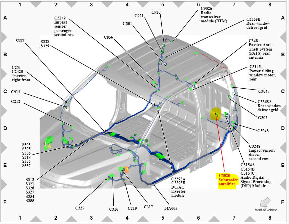
Before we delve into the diagram itself, let’s outline the key components of the 2012 F250's audio system. This will help you understand what the diagram is representing. Key components you'll see referenced in the diagram include:
- Head Unit (Radio): The central control unit, responsible for receiving and processing audio signals. This is where you'll find the main wiring harness connector.
- Speakers: Typically, the F250 has speakers in the front and rear doors, and sometimes tweeters in the A-pillars. The diagram will show the wiring path to each speaker.
- Antenna: Receives radio signals. The antenna wire is usually a single coaxial cable connected to the head unit.
- Amplifier (if equipped): Some F250 models have a factory amplifier, usually located under the seat or behind the dash. The diagram will show the amplifier's input and output wiring.
- Steering Wheel Controls (if equipped): Many F250s have buttons on the steering wheel that control the radio. The diagram will show how these buttons are wired to the head unit.
- SYNC Module (if equipped): Ford's SYNC system allows for hands-free calling and other features. The SYNC module communicates with the head unit, and the diagram will show the wiring connections.
- Wiring Harnesses: The bundles of wires that connect all the components together. The diagram will show the individual wires within each harness.
The wiring harness connecting to the back of the head unit is typically a multi-pin connector containing numerous wires of varying gauges (thickness) and colors. Common wire gauges found are 16AWG, 18AWG and 20AWG. The connector will be clearly identified in the diagram.
Understanding the Symbols
The wiring diagram isn't just a bunch of lines and colors; it's a standardized representation of the electrical system. Understanding the symbols is crucial to interpreting the diagram correctly.
- Lines: Lines represent wires. Thicker lines often indicate wires carrying higher current. Dashed lines may indicate shielded wires or wires that are optional (depending on the vehicle configuration).
- Colors: Each wire has a specific color code. The diagram will include a key that explains what each color represents (e.g., Red = +12V, Black = Ground, White/Green = Left Front Speaker +). Pay close attention to these color codes, as they're the primary way to identify wires. Common colors include red, black, white, green, blue, yellow, and brown. Often you'll see a primary color with a stripe of a secondary color, for instance, "White/Blue" or "Green/Orange".
- Ground Symbols: The ground symbol (usually a series of horizontal lines decreasing in size) indicates where a wire is connected to the vehicle's chassis for grounding. A good ground is essential for proper electrical function.
- Component Symbols: Each component (radio, speaker, amplifier, etc.) has a specific symbol. These symbols are usually labeled with the component's name or a reference designator.
- Connector Symbols: Connectors are represented by rectangles or circles with pins inside. The diagram will often show the pin numbers on the connector, which is crucial for identifying the correct wires.
- Fuses and Relays: Fuses are represented by a wavy line inside a rectangle. Relays are represented by a coil symbol and a switch symbol. The diagram will show the location of the fuses and relays in the circuit.
Important: Always refer to the diagram's legend or key to understand the specific symbols and color codes used. Different diagrams may use slightly different conventions.
How It Works: The Electrical Flow
The 2012 F250's audio system works by taking an input signal (from the radio, CD player, or other source), amplifying it (either by the head unit's built-in amplifier or an external amplifier), and then sending the amplified signal to the speakers. The wiring diagram shows the entire path of this signal, from the power source to the speakers.
Here's a simplified breakdown:
- Power: The head unit receives power from the vehicle's battery, typically through a fused circuit. The diagram will show which fuse protects the radio circuit.
- Ground: The head unit is grounded to the vehicle's chassis. A good ground connection is essential for proper operation.
- Input Signal: The head unit receives audio signals from various sources, such as the radio tuner, CD player, or auxiliary input.
- Amplification: The head unit amplifies the audio signal. In some models, the amplified signal is sent directly to the speakers. In others, the signal is sent to an external amplifier for further amplification.
- Output Signal: The amplified signal is sent to the speakers through speaker wires. The diagram will show the polarity of the speaker wires (+ and -).
Real-World Use: Basic Troubleshooting Tips
The wiring diagram is your best friend when troubleshooting audio problems. Here are a few common scenarios and how the diagram can help:
- No Power to Radio: Use the diagram to locate the fuse for the radio circuit. Check the fuse to see if it's blown. If the fuse is good, use a multimeter to check for voltage at the radio's power wire. If there's no voltage, trace the wire back to the fuse box, checking for breaks or loose connections along the way.
- Speaker Not Working: Use the diagram to identify the speaker wires for the affected speaker. Check the speaker wires for continuity using a multimeter. If there's no continuity, the wire is broken. Also, check the speaker itself to make sure it's not blown.
- Static or Distortion: This could be caused by a poor ground connection. Use the diagram to locate the radio's ground wire. Make sure the ground connection is clean and tight.
- Aftermarket Amplifier Installation: The diagram is essential for tapping into the correct speaker wires and power source for your aftermarket amplifier.
Safety First: Highlighting Risky Components
Working with car electronics can be dangerous if you're not careful. Here are a few safety precautions to keep in mind:
- Disconnect the Battery: Before working on any electrical components, disconnect the negative terminal of the battery. This will prevent accidental shorts and shocks.
- Identify Power Wires: The diagram will clearly identify the power wires. Be extremely careful when working with these wires, as they can carry a significant amount of current.
- Use a Multimeter: A multimeter is an essential tool for testing voltage and continuity. Use it to verify that wires are de-energized before working on them.
- Don't Cut Wires Blindly: Always refer to the wiring diagram before cutting any wires. Make sure you know exactly what the wire is for before cutting it.
- Use Proper Crimping Tools: When making wire connections, use proper crimping tools to ensure a secure and reliable connection.
- Insulate Connections Properly: After making wire connections, insulate them properly with electrical tape or heat shrink tubing to prevent shorts.
Warning: The 2012 Ford F250's electrical system contains components that can be dangerous if mishandled. If you're not comfortable working with electricity, it's best to leave the repairs to a qualified technician.
This guide provides a solid foundation for understanding and using the 2012 Ford F250 radio wiring harness diagram. With a careful approach and the right tools, you can tackle a wide range of audio system repairs and upgrades.
Disclaimer: This information is intended for informational purposes only and should not be considered a substitute for professional advice. Always consult with a qualified technician before performing any repairs or modifications to your vehicle's electrical system.
We have the complete 2012 Ford F250 Radio Wiring Harness Diagram file ready for you to download. It's in a high-resolution PDF format for easy viewing and printing. This diagram will be an invaluable resource for your repair or upgrade project. Just click the download link below to get your copy!