2012 Gmc Acadia Radio Wiring Diagram
The 2012 GMC Acadia radio wiring diagram is your Rosetta Stone for understanding the complex electrical system powering your infotainment. Whether you're tackling a speaker upgrade, diagnosing a parasitic drain, or simply trying to understand how everything connects, this diagram is indispensable. This article breaks down the diagram's intricacies, empowering you to confidently navigate your Acadia's audio system.
Purpose of the Wiring Diagram
Why bother with a wiring diagram? Several reasons make it a vital tool:
- Repairs: Identifying faulty wiring, shorts, or opens becomes far easier. Instead of blindly probing wires, you can pinpoint the exact location of the problem.
- Upgrades & Modifications: Planning to install a new amplifier, subwoofer, or aftermarket head unit? The diagram shows you which wires to tap into and where to find the appropriate signals (e.g., remote turn-on, speaker outputs).
- Troubleshooting Electrical Issues: A seemingly unrelated electrical problem might stem from a malfunctioning radio component. The diagram helps you trace the circuit and isolate the root cause.
- Understanding the System: For those who simply want to learn more about their vehicle, the wiring diagram provides a comprehensive overview of the audio system's architecture.
Key Specs and Main Parts of the 2012 GMC Acadia Radio System
Before diving into the diagram itself, let's establish some context about the 2012 Acadia's audio system. The system varies depending on the trim level and optional packages, but some common components include:
- Head Unit (Radio): The central control unit for the entire audio system. It handles tuner functions (AM/FM), CD playback (if equipped), satellite radio (if equipped), and input selection (AUX, USB).
- Amplifier: Some Acadia models feature a dedicated amplifier, separate from the head unit. This amplifier boosts the audio signal before it's sent to the speakers, resulting in higher volume and improved sound quality. If equipped, the amplifier is often located under the center console or in the rear cargo area.
- Speakers: The Acadia typically has speakers in the front doors, rear doors (if equipped), and potentially a subwoofer. The number and placement of speakers vary by trim level.
- OnStar Module: The OnStar system integrates with the audio system for voice prompts and hands-free calling.
- Steering Wheel Controls: Many Acadia models have steering wheel-mounted controls for adjusting volume, changing stations, and answering phone calls.
- Wiring Harnesses: These bundles of wires connect all the components of the audio system. Connectors at each end ensure proper connections between components.
- Antenna: Receives radio signals (AM/FM, satellite).
Key Specifications to consider:
- Voltage: The audio system operates on the vehicle's 12V DC electrical system.
- Impedance: Speakers typically have an impedance of 4 ohms or 2 ohms. Using speakers with the wrong impedance can damage the amplifier.
- Wattage: The amplifier's output wattage determines how loud the speakers can play.
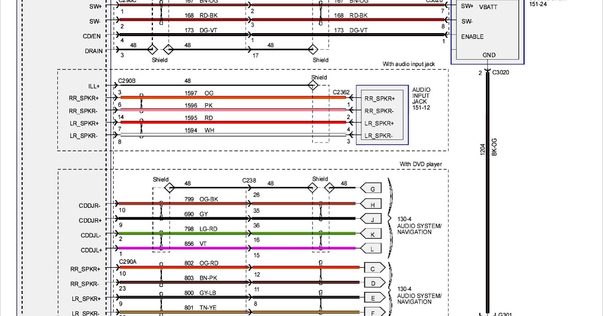
Understanding the Symbols in the Wiring Diagram
The wiring diagram uses a standardized set of symbols to represent electrical components and connections. Understanding these symbols is crucial for interpreting the diagram correctly.
- Lines: Solid lines represent wires. Dashed lines often indicate shielded cables or ground connections. The thickness of the line doesn't typically indicate wire gauge.
- Colors: Each wire is identified by a color code (e.g., RED, BLU, GRN). These codes help you quickly identify the correct wire in the vehicle. Common abbreviations are used, such as "LT BLU" for Light Blue.
- Connectors: Connectors are represented by various shapes, often circles or rectangles with pins inside. Each connector has a unique identifier, such as "X1" or "C201," which is referenced in the diagram.
- Ground Symbols: A ground symbol (often three horizontal lines decreasing in size) indicates a connection to the vehicle's chassis, which serves as the common ground for the electrical system.
- Component Symbols: Specific symbols represent components like the radio, amplifier, speakers, and OnStar module. The diagram should include a legend explaining each symbol. Resistors are zigzag lines, capacitors are two parallel lines, and diodes are triangles pointing towards a line.
- Fuses: Fuses are represented by a small rectangle with a number inside, indicating the fuse's amperage rating.
Important Note: Pay close attention to the wire colors and connector numbers. These are essential for correctly identifying the wires and connectors in your Acadia.
How the 2012 GMC Acadia Radio Wiring Works
The basic flow of the audio system is as follows:
- Power Supply: The head unit and amplifier (if equipped) receive power from the vehicle's battery through a fuse. A dedicated ground connection ensures proper operation.
- Input Signals: The head unit receives input signals from various sources, such as the AM/FM antenna, CD player, satellite radio receiver, AUX input, and USB port.
- Signal Processing: The head unit processes the input signals, applies volume and tone controls, and sends the resulting audio signal to the amplifier (if equipped) or directly to the speakers.
- Amplification: The amplifier (if equipped) boosts the audio signal to a higher power level.
- Speaker Output: The amplified audio signal is sent to the speakers, which convert the electrical signal into sound waves.
- Control Signals: The head unit receives control signals from the steering wheel controls and the OnStar module.
The wiring diagram illustrates the connections between these components, showing the specific wires and connectors used for each signal path. It also shows how the OnStar system is integrated into the audio system, allowing it to override the radio for voice prompts and hands-free calling.
The Body Control Module (BCM) plays a crucial role by controlling the power supply to the radio (preventing parasitic drain) and also sending data signals for features like the radio's anti-theft system. The diagram will show these connections, typically using data bus symbols.
Real-World Use: Basic Troubleshooting Tips
Here are some common problems and how the wiring diagram can help:
- No Power to Radio: Check the fuses related to the radio (often labeled "Radio" or "ACC"). If the fuses are good, use the wiring diagram to trace the power wire from the fuse box to the head unit. Use a multimeter to check for voltage at the head unit connector. If there's no voltage, there's a break in the wire or a faulty connection.
- Speaker Not Working: Use the diagram to identify the speaker wires for the affected speaker. Check the speaker connections for corrosion or loose wires. Use a multimeter to check the resistance of the speaker. An open circuit indicates a faulty speaker. Trace the speaker wires back to the amplifier (if equipped) or the head unit to check for a broken wire or a faulty connection.
- Parasitic Drain: If your battery keeps dying overnight, the radio could be the culprit. Use the wiring diagram to identify the power wires connected to the radio and amplifier. Use a multimeter to measure the current draw when the vehicle is turned off. A high current draw indicates a potential problem with the radio or amplifier.
- Aftermarket Amplifier Installation: The diagram helps identify the correct wires for the remote turn-on, power, ground, and signal inputs/outputs. Carefully identify the speaker wires to avoid damaging the factory system.
Safety Considerations
Working with automotive electrical systems can be dangerous. Always take the following precautions:
- Disconnect the Battery: Before working on any electrical components, disconnect the negative battery terminal to prevent accidental shorts and electrical shocks.
- Use Proper Tools: Use insulated tools designed for automotive electrical work.
- Avoid Working in Wet Conditions: Never work on electrical systems in wet conditions.
- Identify Airbag Wires: Be extremely careful when working near airbag components. Accidental activation of an airbag can cause serious injury. The wiring diagram will show the airbag system's wiring, which you should avoid disturbing unless you are specifically working on the airbag system and are qualified to do so. Airbag wires are often bright yellow or orange and clearly labeled.
- Capacitors inside the radio and amplifier can hold a charge even after the battery is disconnected. Discharge them properly before touching any internal components. This is especially important if you are disassembling the radio or amplifier.
- Improper wiring can damage the radio, amplifier, and other electrical components. Double-check your connections before applying power.
By understanding the 2012 GMC Acadia radio wiring diagram and following these safety guidelines, you can confidently tackle a wide range of audio system projects. Remember to always consult a qualified mechanic if you're unsure about any aspect of the repair or modification process.
We have the 2012 GMC Acadia Radio Wiring Diagram file available for download. This diagram will provide you with a detailed visual representation of the entire audio system. With this resource, you'll have all the information you need to troubleshoot problems, upgrade your system, and gain a deeper understanding of your Acadia's electronics.