2012 Gmc Sierra Radio Wiring Diagram
If you're diving into the audio system of a 2012 GMC Sierra, a radio wiring diagram is your best friend. Whether you're upgrading speakers, installing a new head unit, diagnosing a blown fuse, or simply trying to understand how your truck's audio is wired, having a clear, comprehensive diagram saves you time, frustration, and potential electrical mishaps. This article will serve as your guide to understanding the 2012 GMC Sierra radio wiring diagram, offering insights into its key components, how it works, and how to use it effectively for troubleshooting and upgrades.
Purpose of the 2012 GMC Sierra Radio Wiring Diagram
The wiring diagram is a visual representation of the electrical connections within the radio and audio system of your 2012 GMC Sierra. It illustrates the flow of current between different components, specifies wire colors, and identifies connectors. The primary reasons to consult such a diagram include:
- Repairing a Faulty System: Identifying broken wires, short circuits, or malfunctioning components.
- Upgrading Audio Components: Safely installing new speakers, amplifiers, or a new head unit without damaging existing wiring.
- Adding Accessories: Connecting aftermarket devices like subwoofers, satellite radios, or hands-free kits.
- Learning and Understanding: Gaining a better understanding of your vehicle's electrical system and how the radio integrates into it.
Key Specs and Main Parts of the 2012 GMC Sierra Radio System
The 2012 GMC Sierra radio system, depending on the trim level, might include several variations. However, some core components remain consistent. Understanding these helps in navigating the wiring diagram:
- Head Unit (Radio): This is the central control unit, responsible for receiving radio signals, playing CDs (if equipped), processing audio, and controlling other functions like Bluetooth connectivity (if equipped). Different trims may have base models or premium Bose systems.
- Speakers: Typically, the Sierra will have speakers in the front doors, rear doors (if a Crew Cab or Extended Cab), and potentially tweeters in the A-pillars (depending on the audio package).
- Amplifier: In premium audio systems (like those with Bose), a separate amplifier boosts the audio signal before it reaches the speakers. This is usually located under the center console or behind the rear seat.
- Antenna: Receives radio signals and transmits them to the head unit.
- Wiring Harnesses: Bundles of wires that connect all the components together. These harnesses often have specific connectors that plug into the back of the head unit, the amplifier, and the speakers.
- Grounding Points: Crucial connection points where wires are attached to the vehicle's chassis, providing a return path for the electrical current.
- Fuse Box: Contains fuses that protect the radio and audio system components from overcurrent situations. The radio fuse is usually located in the instrument panel fuse box or the under-hood fuse box.
Symbols and Conventions in the Wiring Diagram
Wiring diagrams utilize standardized symbols to represent various components and connections. Understanding these symbols is essential for accurate interpretation:
- Lines: Solid lines represent wires. Dashed lines may represent shielded cables or less critical connections.
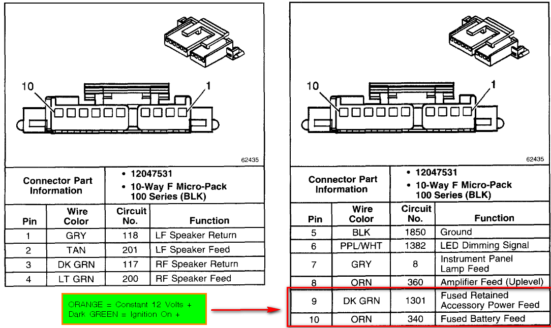
- Wire Colors: Each wire is assigned a specific color, indicated by abbreviations such as "BLU" for blue, "RED" for red, "GRN" for green, "BLK" for black, "WHT" for white, "YEL" for yellow, etc. Sometimes, a wire may have a primary color and a stripe, like "BLU/WHT" for a blue wire with a white stripe.
- Component Symbols: Each component, like a speaker, resistor, capacitor, or connector, has its own standardized symbol.
- Connectors: Represented by rectangles or circles with numbers indicating the pin assignments. These numbers correspond to the pins on the physical connector.
- Ground Symbols: Indicate the grounding points where wires are connected to the vehicle's chassis.
It's critical to consult the legend provided with the specific diagram. The legend translates all the symbols, abbreviations, and color codes used in that diagram. Without it, interpretation is nearly impossible.
How the 2012 GMC Sierra Radio System Works
The radio system functions as follows:
- The antenna receives radio waves and sends them to the head unit.
- The head unit processes the radio signal (or reads from a CD/MP3 player/Bluetooth device) and generates an audio signal.
- If the system has a separate amplifier, the head unit sends a low-level audio signal (pre-out) to the amplifier. The amplifier boosts this signal. In systems without a separate amplifier, the head unit itself provides the amplification.
- The amplified audio signal is then sent to the speakers.
- The speakers convert the electrical signal into sound waves.
- The entire system is powered by the vehicle's electrical system and protected by fuses.
The wiring diagram illustrates the exact path that the electrical signal takes through this process.
Real-World Use: Basic Troubleshooting Tips
Here's how you can use the wiring diagram to troubleshoot common radio problems:
- No Power to Radio: Use the diagram to locate the radio fuse. Check if the fuse is blown. If it is, replace it. If the fuse blows again immediately, there's a short circuit in the wiring. The diagram helps you trace the power wire and identify potential points of failure. Use a multimeter to test for voltage at the radio's power connector.
- Speaker Not Working: Use the diagram to identify the wires that connect to the non-working speaker. Check the speaker terminals for continuity (using a multimeter). If there's no continuity, the speaker is likely blown. Also, check the wiring for damage or loose connections.
- Distorted Sound: This could be caused by a faulty speaker, a problem with the amplifier (if equipped), or a wiring issue. Use the diagram to check the speaker wires for shorts or damage.
- Installation of Aftermarket Stereo: The wiring diagram will show you each wire's function, allowing you to properly connect the new stereo to the truck's wiring harness. Always use a wiring harness adapter to avoid cutting the original factory harness.
Always disconnect the negative terminal of the battery before working on the electrical system.
Safety Considerations
Working with automotive electrical systems can be dangerous. Here are some crucial safety precautions:
- Disconnect the Battery: Always disconnect the negative (black) terminal of the battery before working on the radio or any other electrical component. This prevents accidental shorts and electrical shock.
- Identify Airbag Wiring: Be extremely cautious when working near airbag wiring. Accidentally triggering an airbag can cause serious injury. Consult the wiring diagram to identify these circuits and avoid disturbing them. If unsure, seek professional assistance.
- Use Proper Tools: Use insulated tools to prevent electrical shock.
- Avoid Cutting Wires Unnecessarily: Always try to use wiring harness adapters when installing aftermarket components. This allows you to revert to the original configuration if needed.
- Double-Check Connections: Before reconnecting the battery, double-check all connections to ensure they are secure and properly insulated.
The airbag system wiring is often bright yellow or orange, making it easily identifiable; however, do not rely solely on color. Always consult the wiring diagram.
While this article provides a general guide, specific wiring configurations can vary based on the 2012 GMC Sierra's trim level and options. It is always recommended to consult the specific wiring diagram for your vehicle's VIN.
We have the 2012 GMC Sierra Radio Wiring Diagram readily available for download. Ensure you consult it frequently and double-check against the specifics of your truck before undertaking any work. It will provide the exact and necessary details for a successful project.