2012 Gmc Terrain 4cyl Cooling System Diagram Coolant System
Understanding the cooling system in your 2012 GMC Terrain 4-cylinder is crucial for maintaining its health and preventing costly engine damage. This article delves into the coolant system diagram, explaining its components, function, and how to use it for diagnostics and repairs. Consider this your comprehensive guide to keeping your Terrain's engine running cool.
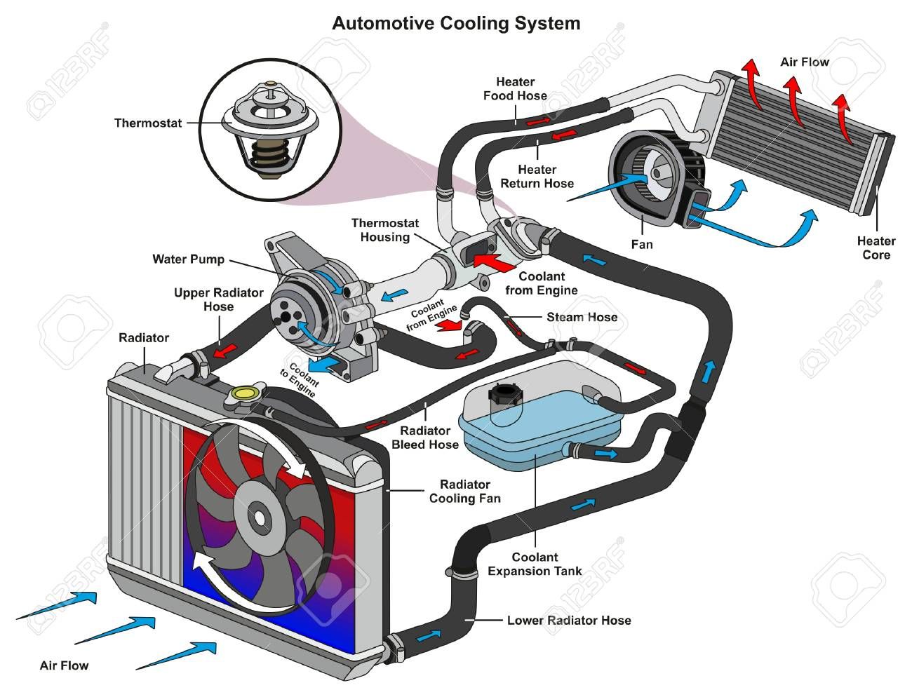
Purpose of the Cooling System Diagram
The cooling system diagram is more than just a pretty picture; it's an invaluable tool. It serves several key purposes:
- Repair & Maintenance: When diagnosing overheating issues, coolant leaks, or thermostat problems, the diagram helps you pinpoint the location of components, hoses, and sensors.
- Component Identification: Quickly identify parts like the water pump, radiator, heater core, and various sensors. Understanding their placement is key for replacement or inspection.
- System Understanding: Gain a comprehensive understanding of how the entire cooling system works together. This knowledge allows for more informed troubleshooting and preventative maintenance.
- Modifications & Upgrades: If you're considering performance upgrades or modifications to the cooling system (e.g., adding an auxiliary cooler), the diagram provides a visual layout for planning and execution.
- Reference Material: A handy reference for future work, especially when dealing with obscure parts or hose routing.
We have a downloadable PDF of the 2012 GMC Terrain 4-cylinder cooling system diagram available for your reference. This will be immensely helpful as you follow along with this guide.
Key Specs and Main Parts
The 2012 GMC Terrain 4-cylinder typically utilizes a pressurized liquid cooling system with a specific coolant mixture (typically a 50/50 mix of antifreeze and distilled water). Understanding the main components is fundamental to understanding the diagram.
- Radiator: The primary heat exchanger. Coolant flows through the radiator's core, and air passing through the fins dissipates heat.
- Water Pump: A mechanical or electrical pump that circulates coolant throughout the engine and cooling system. Driven by the engine's serpentine belt.
- Thermostat: A temperature-sensitive valve that regulates coolant flow to the radiator. It ensures the engine reaches its optimal operating temperature quickly and maintains it.
- Coolant Reservoir (Overflow Tank): Provides a place for coolant to expand as it heats up and to be drawn back into the system as it cools.
- Coolant Hoses: Rubber hoses that connect various components of the cooling system, allowing coolant to flow freely.
- Heater Core: A small radiator located inside the vehicle's cabin that provides heat.
- Radiator Fan: An electric fan that pulls air through the radiator when the vehicle is stationary or moving slowly.
- Temperature Sensors: Engine Coolant Temperature (ECT) sensor provides temperature readings to the engine control unit (ECU) for engine management.
Key Specs:
- Coolant Type: Dex-Cool (or equivalent OAT - Organic Acid Technology coolant)
- Coolant Capacity: Approximately 7.5 quarts (check your owner's manual for precise capacity).
- Thermostat Opening Temperature: Typically around 180-195°F (82-90°C).
- System Pressure: Radiator cap is typically rated for around 15-18 PSI.
Understanding the Symbols in the Diagram
Cooling system diagrams use standard symbols to represent different components and fluid flow. Being able to decipher these symbols is crucial for using the diagram effectively.
- Solid Lines: Generally represent coolant hoses or pipes. The thickness of the line may indicate the diameter of the hose.
- Dashed Lines: Often represent vacuum lines, electrical wiring, or control signals related to the cooling system.
- Arrows: Indicate the direction of coolant flow. Very important for understanding the circuit.
- Colors: Colors are often used to differentiate between different types of fluids or circuits. In some diagrams:
- Blue: May represent cool coolant flow.
- Red: May represent hot coolant flow.
- Green/Yellow: May represent sensor wiring.
- Component Symbols: Standardized symbols represent each component:
- Radiator: Typically depicted as a rectangular shape with wavy lines inside.
- Water Pump: Often shown as a circle with an impeller symbol.
- Thermostat: Displayed as a valve symbol.
- Coolant Reservoir: Usually a simple tank shape.
- Sensors: Rectangles or circles with electrical symbols attached.
How the Cooling System Works
The cooling system's primary function is to maintain the engine at its optimal operating temperature. Here's a breakdown of the process:
- Coolant Circulation: The water pump circulates coolant through the engine block and cylinder head. This coolant absorbs heat generated by combustion.
- Thermostat Regulation: When the engine is cold, the thermostat remains closed, preventing coolant from flowing to the radiator. This allows the engine to warm up quickly.
- Reaching Operating Temperature: Once the engine reaches its operating temperature, the thermostat begins to open, allowing coolant to flow to the radiator.
- Heat Dissipation: As coolant flows through the radiator, air passing through the radiator fins dissipates heat to the atmosphere.
- Return to Engine: The cooled coolant returns to the engine to continue the cycle.
- Overflow Tank: As the coolant heats, it expands. Excess coolant flows into the coolant reservoir. As the engine cools, coolant is drawn back into the system from the reservoir.
- Heater Core Function: A portion of the hot coolant is routed through the heater core. The blower fan forces air across the heater core, providing warm air for the vehicle's cabin.
Real-World Use: Basic Troubleshooting Tips
The cooling system diagram is an indispensable tool for diagnosing cooling system problems. Here are some common issues and how the diagram can help:
- Overheating: Check coolant level, radiator for blockages, thermostat operation, water pump functionality (look for leaks or noise), and radiator fan operation. Use the diagram to locate each component quickly.
- Coolant Leaks: Inspect all hoses, connections, and components (water pump, radiator, thermostat housing) for leaks. The diagram helps you trace the coolant path and identify potential leak points. Look for dried coolant residue (often orange or green).
- No Heat: Check coolant level, thermostat operation, and heater core hoses for blockages. The diagram will help you locate the heater core and its associated hoses.
- Low Coolant Level: Visually inspect the entire system using the diagram as a reference. Then, pressure test the system with a pressure tester.
Example: If you suspect a faulty thermostat, the diagram will show you its exact location, allowing you to access it for testing or replacement. You can verify hose routing and connections before disassembly, ensuring correct reassembly.
Safety Precautions
Working on the cooling system can be dangerous if proper precautions are not taken. Always remember:
- Hot Coolant: Never open the radiator cap or any part of the cooling system while the engine is hot. The system is pressurized, and hot coolant can spray out, causing severe burns. Wait for the engine to cool down completely.
- Electrical Components: Disconnect the negative battery terminal before working on any electrical components related to the cooling system, such as the radiator fan or temperature sensors.
- Toxic Coolant: Coolant is toxic. Avoid contact with skin and eyes. Clean up any spills immediately. Dispose of used coolant properly at a recycling center.
- Fan Blades: Be extremely careful around the radiator fan. It can start unexpectedly, even when the engine is off (especially if the A/C is on). Disconnect the fan's electrical connector before working near it.
The radiator cap is a high-risk component. Remove it slowly and carefully, wearing eye protection and gloves, to relieve pressure gradually. Never remove it while the engine is hot.
By using the cooling system diagram in conjunction with safe practices, you can confidently diagnose and repair issues, keeping your 2012 GMC Terrain running smoothly. Remember to consult your vehicle's service manual for specific torque specifications and procedures.