2012 Hyundai Sonata Fuse Box Diagram
Alright, let's dive into the 2012 Hyundai Sonata fuse box diagram. If you're looking to diagnose electrical issues, customize your ride, or just get a better understanding of your Sonata's inner workings, this diagram is absolutely crucial. Forget blindly poking around with a multimeter; this roadmap saves you time, money, and potential headaches.
Purpose of the Fuse Box Diagram
The fuse box diagram serves several key purposes:
- Troubleshooting Electrical Problems: When an electrical component fails – a light, the radio, or even the engine starting system – the fuse box is one of the first places you should check. The diagram pinpoints which fuse controls that component.
- Safe Modifications: Adding aftermarket accessories (lights, amplifiers, etc.) requires tapping into the electrical system. The diagram helps you identify appropriate circuits and fuse sizes to avoid overloading the system and creating a fire hazard.
- General Understanding of the Electrical System: Even if nothing is broken, studying the diagram gives you a solid overview of how the electrical system is organized, which is valuable knowledge for any car owner.
- Preventative Maintenance: Periodically checking fuses, especially those prone to issues, can help you identify potential problems before they escalate into larger, more costly repairs.
Key Specs and Main Parts of the 2012 Sonata Fuse Boxes
The 2012 Sonata actually has multiple fuse boxes. We'll focus on the two main ones:
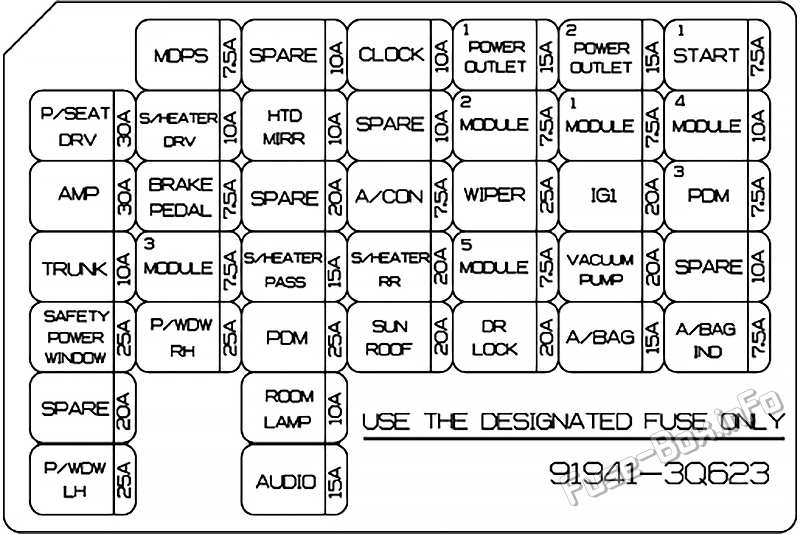
- Interior Fuse Box (Under the Dashboard): Located typically on the driver's side, under the dashboard. This box primarily handles circuits for interior components like the infotainment system, lights, power windows, and power locks. Access requires removing a small panel, usually by unclipping it.
- Engine Compartment Fuse Box: Found in the engine bay, typically near the battery. This box controls circuits for critical engine components, headlights, ABS, and other vital systems. It’s usually housed in a sealed plastic container to protect against moisture and debris.
Key Specs to consider:
- Fuse Types: The 2012 Sonata typically uses blade-type fuses (ATO/ATC, Mini, and Low Profile Mini). Each type has a different physical size and current rating. It’s critical to replace a blown fuse with one of the same type and amperage.
- Amperage Ratings: Fuses are rated in Amperes (A), indicating the maximum current they can handle before blowing. Common ratings range from 5A to 30A or higher. The diagram clearly shows the correct amperage for each fuse.
- Relays: Relays are electromechanical switches that control high-current circuits using a low-current signal. They are often found alongside fuses in the fuse box and are responsible for controlling components like the fuel pump, starter motor, and headlights.
Understanding the Symbols on the Diagram
Fuse box diagrams use standardized symbols and conventions. Learning these symbols is key to interpreting the diagram correctly:
- Fuse Symbol: A wavy line enclosed in a rectangle represents a fuse. The amperage rating is usually printed directly next to or below the symbol.
- Relay Symbol: Typically depicted as a coil with a switch contact, indicating the relay's function as an electromechanical switch.
- Line Thickness: Line thickness can sometimes indicate the gauge (size) of the wire in the circuit. Thicker lines often represent wires carrying higher currents.
- Color Coding (in some diagrams): Some diagrams use color coding to differentiate between circuits. However, color coding on the diagram might not perfectly match the actual wire colors in the car, so exercise caution. Black is generally ground, red/orange are typically power, and other colors vary depending on the circuit.
- Icons: Many diagrams use small icons to represent the component that a particular fuse protects. For example, a headlight icon indicates the headlight fuse, a radio icon indicates the radio fuse, and so on.
Pay close attention to the legend or key accompanying the diagram. This legend explains the meaning of each symbol and abbreviation used. Without the legend, interpreting the diagram accurately is nearly impossible.
How It Works: The Fuse Protection System
Fuses are sacrificial components designed to protect the electrical system from overcurrent situations. Here’s how it works:
- Normal Operation: Under normal operating conditions, current flows freely through the fuse.
- Overcurrent Condition: If excessive current flows through the circuit (due to a short circuit, a faulty component, or an overload), the fuse's internal element heats up rapidly.
- Fuse Blows: When the element reaches its melting point, it breaks the circuit, stopping the flow of current and preventing damage to other components.
Think of a fuse as a weak link in a chain. It’s intentionally designed to fail first, protecting the more expensive and critical components downstream.
Real-World Use: Basic Troubleshooting Tips
Here's a basic troubleshooting process using the fuse box diagram:
- Identify the Problem: Determine which electrical component is malfunctioning.
- Consult the Diagram: Locate the fuse associated with that component in the diagram (both interior and engine compartment boxes).
- Inspect the Fuse: Remove the fuse using a fuse puller (a small plastic tool designed for this purpose). Visually inspect the fuse. A blown fuse will have a broken or blackened filament inside.
- Test the Fuse (Optional): Use a multimeter set to continuity mode to test the fuse. A good fuse will show continuity (a beep or a low resistance reading). A blown fuse will show no continuity.
- Replace the Fuse: If the fuse is blown, replace it with a new fuse of the exact same type and amperage rating.
- Test the Component: Turn on the component to see if it now works.
- If the Fuse Blows Again: If the new fuse blows immediately or shortly after replacement, there is a persistent overcurrent condition (a short circuit or a faulty component). Further diagnosis is required, which may involve tracing the wiring harness, testing individual components, or seeking professional help.
Safety Considerations
Working with automotive electrical systems can be dangerous. Keep these safety precautions in mind:
- Disconnect the Battery: Before working on any electrical component, always disconnect the negative terminal of the battery. This prevents accidental shorts and electrical shocks.
- Use Proper Tools: Use insulated tools designed for automotive electrical work.
- Never Replace a Fuse with a Higher Amperage: This can overload the circuit and cause a fire. This is extremely important!
- Be Cautious Around Relays: Relays can sometimes be difficult to diagnose. If you're unsure, consult a professional.
- High-Current Circuits: Be extremely cautious when working with high-current circuits like the starter motor or alternator. These circuits can deliver a dangerous electrical shock.
- Avoid Water: Never work on electrical components in wet or damp conditions.
Specifically, the engine compartment fuse box often contains fuses and relays controlling the starter motor, alternator, and fuel pump. These circuits carry significant current and pose a higher risk of electrical shock if mishandled. Proceed with extreme caution.
By understanding the 2012 Hyundai Sonata fuse box diagram and following proper safety precautions, you can confidently diagnose and repair electrical problems, customize your vehicle, and gain a deeper understanding of its electrical system.
We have the complete 2012 Hyundai Sonata fuse box diagram file available for download. It's a high-resolution PDF with both interior and engine compartment fuse layouts. This diagram will give you the clear and detailed information to properly work on your Sonata.