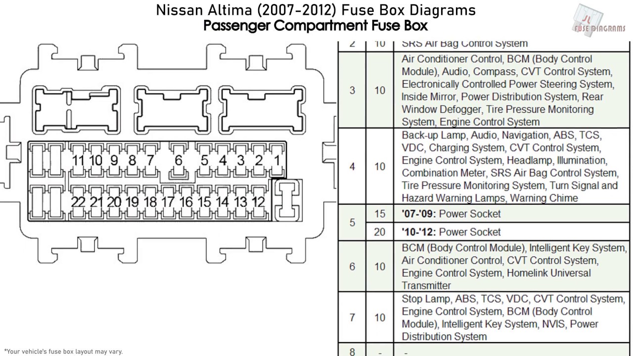
2012 Nissan Altima Fuse Box Diagram
Okay, let's dive into the fuse box diagram for the 2012 Nissan Altima. This guide is designed to help you, the experienced DIYer, understand the intricacies of your Altima's electrical system. We'll break down the diagram, its purpose, and how to use it for troubleshooting. This isn't just about replacing a blown fuse; it's about gaining a deeper understanding of how your car's electrical circuits operate.
Why You Need the Fuse Box Diagram
The fuse box diagram is essentially the Rosetta Stone for your car's electrical system. Its main purpose is to identify and locate each fuse and relay in your Altima's fuse boxes. Why is this important? Several reasons:
- Troubleshooting Electrical Problems: When an electrical component fails (e.g., a taillight, the radio, the power windows), the first place to check is the fuse box. A blown fuse is a common culprit and easily identified using the diagram.
- Modifying Your Car: Planning to install aftermarket accessories like a new sound system, auxiliary lights, or a dashcam? You'll need to tap into existing circuits. The diagram helps you identify the correct fuses to avoid overloading the system.
- Preventative Maintenance: Regularly checking the fuses can help identify potential issues before they become major problems. For example, a fuse that consistently blows might indicate a short circuit or an overloaded circuit.
- General Understanding: Even if you're not currently experiencing problems, understanding the fuse box layout gives you a better overall knowledge of your vehicle's systems.
Key Specs and Main Parts of the 2012 Altima Fuse Boxes
The 2012 Nissan Altima typically has two main fuse box locations:
- Interior Fuse Box: Located inside the cabin, usually under the dashboard on the driver's side. This box primarily houses fuses for interior components like the radio, interior lights, power windows, and other comfort features.
- Engine Compartment Fuse Box: Located in the engine bay, near the battery. This box contains fuses and relays for critical engine components like the fuel pump, ignition system, headlights, and ABS.
Key Specs:
- Fuse Types: The 2012 Altima primarily uses blade-type fuses. These fuses come in different sizes (e.g., mini, standard, maxi) and amp ratings. Amp rating is crucial; you must replace a blown fuse with one of the same amp rating to prevent damage to the circuit or fire hazards.
- Relays: Relays are electromechanical switches that control high-current circuits using a low-current signal. They are often used for components like the fuel pump, starter motor, and headlights.
- Fuse Puller: A small plastic tool (usually included in the fuse box) used to safely remove fuses without damaging them or yourself.
Decoding the Fuse Box Diagram: Symbols, Lines, and Colors
Understanding the symbols on the diagram is crucial for correct interpretation. Here's a breakdown:
- Fuses: Represented by a rectangular box with a number indicating its amp rating (e.g., "10A" for a 10-amp fuse).
- Relays: Usually depicted as a square or rectangular symbol with internal wiring shown. The diagram might also indicate the relay's function (e.g., "Fuel Pump Relay").
- Lines: Solid lines represent the electrical circuits. The thickness of the line sometimes, but not always, indicates the gauge (thickness) of the wire.
- Colors: While most diagrams are black and white, some may use colors to differentiate between different circuit types. If colors are used, a legend will explain their meaning.
- Component Icons: Small icons may represent the component the fuse protects (e.g., a light bulb icon for headlights, a steering wheel icon for power steering).
- Ground Symbols: Usually represented by a series of descending horizontal lines, indicating the point where the circuit connects to the vehicle's chassis for grounding.
The diagram will typically show the fuse number or ID (e.g., "Fuse #12"), its amp rating, and the component it protects (e.g., "Interior Lights"). The diagram is usually organized based on the fuse box location (Interior or Engine Compartment).
How It Works: From Battery to Component
Let's trace a simple circuit to understand how the system works:
- Power Source: The circuit begins at the battery, which provides the electrical power.
- Fuse: The power flows from the battery, usually through the main fuse box, and then branches out to individual circuits. Each circuit is protected by a fuse.
- Switch/Relay: The power then flows through a switch (e.g., the headlight switch) or a relay (controlled by a switch). This allows you to turn the component on or off.
- Component: After the switch or relay, the power reaches the electrical component (e.g., the headlight bulb).
- Ground: Finally, the circuit completes by returning to the battery through the vehicle's chassis (ground).
The fuse acts as a sacrificial element. If there's a short circuit or overload (too much current flowing through the circuit), the fuse will blow, interrupting the circuit and preventing damage to the component and wiring. This prevents overheating, fires, and other serious electrical problems.
Real-World Use: Basic Troubleshooting Tips
Here's how to use the fuse box diagram for basic troubleshooting:
- Identify the Problem: What component isn't working? (e.g., the radio, a headlight, the windshield wipers).
- Consult the Diagram: Locate the fuse box diagram (usually on the inside of the fuse box cover or in the owner's manual). Find the fuse associated with the malfunctioning component.
- Inspect the Fuse: Use the fuse puller to remove the fuse. Visually inspect it. A blown fuse will typically have a broken filament (the thin wire inside the fuse). Some fuses may have a darkened or melted appearance.
- Replace the Fuse: Replace the blown fuse with a new fuse of the same amp rating. Never use a fuse with a higher amp rating, as this could overload the circuit and cause damage or a fire.
- Test the Component: Turn on the component to see if it now works.
- If the Fuse Blows Again: If the new fuse blows immediately or shortly after being replaced, this indicates a more serious problem, such as a short circuit. You'll need to investigate further, possibly using a multimeter to check for continuity and voltage. Seek professional help if you're not comfortable with electrical diagnostics.
Safety First: Identifying Risky Components
Working with electrical systems can be dangerous. Here are some key safety precautions:
- Disconnect the Battery: Before working on any electrical components, disconnect the negative terminal of the battery. This prevents accidental shorts and shocks.
- High-Current Circuits: Be especially careful around high-current circuits, such as the starter motor and alternator circuits. These circuits can deliver a powerful shock.
- Airbag Systems: Never tamper with airbag systems unless you are properly trained and have the necessary equipment. Airbags can deploy unexpectedly and cause serious injury.
- Fuel Pump Circuits: When working on fuel pump circuits, be aware of the risk of fuel spills and fire. Work in a well-ventilated area and avoid sparks or open flames.
- Proper Tools: Use insulated tools to prevent accidental shorts.
- Consult a Professional: If you're unsure about any aspect of the electrical system, consult a qualified mechanic.
Remember, the fuse box diagram is a valuable tool for understanding and troubleshooting your 2012 Nissan Altima's electrical system. By understanding the symbols, circuits, and safety precautions, you can confidently tackle basic electrical repairs and modifications.
We have a detailed, printable version of the 2012 Nissan Altima fuse box diagram available for download. It contains high-resolution images and clear labels to assist you with your projects. Feel free to use it as a handy reference guide in your garage!