2012 Nissan Pathfinder Engine Wiring Harness
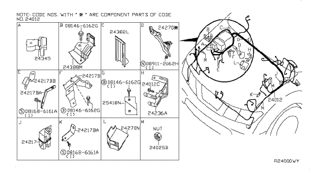
Alright, let's dive into the engine wiring harness for the 2012 Nissan Pathfinder. This is the nervous system of your engine, and understanding it is crucial for anything from basic repairs to more complex modifications. Whether you're chasing down a pesky check engine light, planning an upgrade, or just want to get a better grasp of your vehicle's inner workings, knowing your way around this diagram is a huge asset.
Purpose of Understanding the Wiring Harness
Why bother with a wiring diagram? Well, the engine wiring harness is the central pathway for all electrical signals powering and controlling vital engine components. This includes everything from the fuel injectors and ignition coils to the sensors that report engine performance to the ECU (Engine Control Unit, the engine's computer). Understanding the harness allows you to:
- Troubleshoot electrical problems: Pinpoint breaks in circuits, shorts to ground, or open circuits.
- Perform maintenance: Inspect connections for corrosion or damage.
- Modify your vehicle: Safely add aftermarket components, such as performance chips or auxiliary lighting.
- Understand engine operation: Gain a deeper understanding of how the various components of the engine interact.
Key Specs and Main Parts of the 2012 Pathfinder Engine Wiring Harness
The 2012 Nissan Pathfinder, depending on the model, typically came with a 4.0L V6 (VQ40DE) engine. Therefore, we will focus on that. The wiring harness will be specific to this engine. While exact specifications can vary slightly depending on trim level (e.g., 2WD vs. 4WD), the fundamental architecture remains largely the same.
Here are some key components and specifications you should be aware of:
- ECU Connectors: These are the main connection points for the harness, sending and receiving signals from the engine computer.
- Injector Connectors: Individual connectors for each of the six fuel injectors.
- Ignition Coil Connectors: Connectors for each ignition coil pack, responsible for firing the spark plugs.
- Sensor Connectors: Numerous connectors for sensors like the crankshaft position sensor (CKP), camshaft position sensors (CMP), mass airflow sensor (MAF), throttle position sensor (TPS), oxygen sensors (O2 sensors), coolant temperature sensor (CTS), and knock sensor.
- Grounding Points: Critical locations where the harness is grounded to the vehicle's chassis. Poor grounding can cause a multitude of electrical issues.
- Power Supply Wires: These wires provide the necessary voltage to the various components. These typically come directly from the battery or the fuse box.
- Signal Wires: These wires carry sensor data back to the ECU. These are typically low voltage and susceptible to interference.
- Harness Routing: The physical path the harness takes through the engine bay. It's important to know this to prevent damage or chafing.
- Wire Gauge: The thickness of the wires, measured in AWG (American Wire Gauge). Thicker wires are used for higher current loads.
Understanding Wiring Diagram Symbols
Wiring diagrams use a standardized set of symbols to represent electrical components and connections. Mastering these symbols is key to understanding the diagram.
- Lines: Represent wires. Solid lines indicate a direct connection, while dashed lines might indicate a shielded wire or a connection through a connector.
- Colors: Each wire is assigned a color, usually abbreviated (e.g., BLK for black, RED for red, GRN for green, YEL for yellow, BLU for blue, WHT for white). Color codes are crucial for identifying the correct wire. Multiple colors mean a wire has a stripe (e.g., RED/BLK means a red wire with a black stripe).
- Connectors: Represented by various shapes, often circles or rectangles with pins inside. Mating connectors are usually labeled with the same identifier.
- Grounds: Indicated by a symbol resembling an upside-down triangle or a series of lines decreasing in length.
- Fuses: Shown as a small rectangle with a number indicating its amperage rating.
- Relays: Depicted as a coil and a set of contacts.
- Resistors: A zigzag line.
- Diodes: A triangle pointing to a vertical line.
- Sensors: Each type of sensor has its own unique symbol.
- Actuators: Such as fuel injectors, are represented by a rectangle or a circle with specific markings.
How It Works: Following the Current Flow
The basic principle is to trace the flow of current through the circuit. Start with the power source (usually the battery), follow the wire through any fuses, relays, and switches, to the component being powered. Then, trace the return path back to ground. The ECU acts as a central control point, receiving signals from sensors, processing the data, and then sending commands to actuators to control engine operation.
For example, let's consider the fuel injector circuit. Power flows from the battery, through a fuse, to the fuel injector relay. When the ECU activates the relay, power is supplied to the fuel injector. The ECU then controls the injector's opening and closing by grounding the other side of the injector circuit. By varying the grounding duration, the ECU controls the amount of fuel injected into the engine.
Real-World Use: Basic Troubleshooting Tips
Here are some basic troubleshooting tips, assuming you have the wiring diagram:
- Check for Power: Use a multimeter to verify that the component is receiving power.
- Check for Ground: Ensure the component has a good ground connection.
- Check Continuity: Use a multimeter to test the continuity of the wires. This verifies that there are no breaks in the circuit.
- Check for Shorts: Use a multimeter to check for shorts to ground. This indicates that a wire is touching the chassis or another grounded component.
- Visually Inspect: Look for damaged wires, corroded connectors, or loose connections.
- Use a Scan Tool: A scan tool can read diagnostic trouble codes (DTCs) from the ECU, which can help pinpoint the problem area. However, remember that a DTC only points you in the right direction; it doesn't always tell you exactly what's wrong. You'll still need to use the wiring diagram and a multimeter to diagnose the issue properly.
Example: Let's say your 2012 Pathfinder is throwing a code for a faulty MAF sensor. Using the wiring diagram, you can identify the MAF sensor connector and trace the wires back to the ECU. You can then use a multimeter to check for power, ground, and continuity on each wire. If you find a break in the circuit, you can repair or replace the damaged wire. If the wiring is good, the sensor itself may be faulty and need to be replaced.
Safety: Highlighting Risky Components
Working with electrical systems can be dangerous. Here are some safety precautions:
- Disconnect the Battery: Always disconnect the negative battery cable before working on the electrical system. This will prevent accidental shorts and electrical shocks.
- Work in a Well-Ventilated Area: When working with fuel or other flammable liquids, work in a well-ventilated area to prevent the buildup of explosive fumes.
- Use Proper Tools: Use insulated tools to prevent electrical shocks.
- Be Careful with Airbag Connectors: Airbag connectors are usually yellow and require special care. Disconnecting them incorrectly can cause the airbags to deploy, which can be dangerous. Refer to the service manual for proper procedures.
- High-Voltage Components: Be extremely careful around the ignition coils and spark plugs, as these components carry high voltage.
- Fuel Injectors: Fuel injectors contain pressurized fuel. Relieve the fuel pressure before disconnecting the fuel injectors.
Disclaimer: This article provides general information only. Always refer to the official service manual for your specific vehicle for detailed instructions and safety precautions. Incorrectly diagnosing or repairing electrical systems can cause damage to your vehicle or serious injury.
We have the 2012 Nissan Pathfinder engine wiring diagram file available. You can download it for a more detailed and comprehensive understanding of your vehicle's electrical system.