2012 Nissan Sentra Fuse Box Diagram
Let's dive into the fuse box diagram of the 2012 Nissan Sentra. Understanding this diagram is crucial whether you're tackling a minor electrical repair, planning modifications, or simply want to learn more about your vehicle's electrical system. This guide will provide you with the knowledge you need to confidently navigate the Sentra's fuse box and perform basic troubleshooting.
Why Bother with the Fuse Box Diagram?
The fuse box diagram is essentially a roadmap of your car's electrical system. It identifies each fuse and relay, specifying what circuit it protects. Without it, diagnosing electrical problems becomes a guessing game, potentially leading to further damage. This diagram is your best friend for:
- Troubleshooting Electrical Issues: Quickly identify the fuse responsible for a malfunctioning component.
- Performing Modifications: Safely tap into existing circuits for adding accessories like aftermarket stereos or lights.
- Understanding Your Car's Electrical System: Gain a deeper understanding of how your vehicle's various systems are powered and protected.
- Preventing Further Damage: Replacing a blown fuse with the correct amperage rating prevents potential fires and damage to sensitive electronics.
Key Specs and Main Parts
The 2012 Nissan Sentra typically has two main fuse box locations:
- Interior Fuse Box: Located inside the cabin, often under the dashboard on the driver's side or behind a small panel. This fuse box generally houses fuses for interior components like the radio, interior lights, power windows, and accessories.
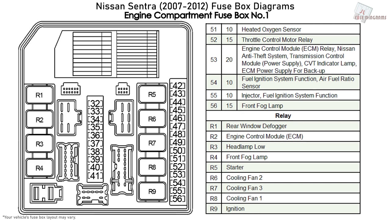
- Engine Compartment Fuse Box: Situated in the engine bay, this fuse box protects vital engine components like the fuel pump, ignition system, and cooling fan. It might be labeled as the 'IPDM E/R' (Intelligent Power Distribution Module Engine Room) in some documentation.
Key Components:
- Fuses: These are safety devices designed to protect electrical circuits from overcurrent. They contain a thin wire that melts and breaks the circuit if the current exceeds a specific rating (measured in amperes or amps). Common fuse types include blade fuses (ATO, Mini, Maxi) and cartridge fuses.
- Relays: Relays are electromechanical switches that use a small electrical current to control a larger current. They are often used to control high-power components like headlights, fuel pumps, and starter motors.
- Circuit Breakers: These are reusable protective devices that trip (open) the circuit when an overcurrent occurs. They can be manually reset once the fault is cleared. While less common than fuses in this era Sentra, they might exist for certain circuits.
- Fuse Box Housing: The plastic enclosure that houses the fuses and relays, providing protection and organization.
- Diagram Label: A sticker or label, usually located inside the fuse box cover, that identifies each fuse and relay by its function and amperage rating. This is the key to understanding the system.
Decoding the Diagram: Symbols, Lines, and Colors
Fuse box diagrams use a standardized set of symbols and conventions to represent electrical components and their connections. Here’s a breakdown of what you might encounter:
Fuse Symbols:
Fuses are generally represented by a rectangular box with a zigzag line inside. The amperage rating (e.g., 10A, 15A, 20A) is usually printed next to the symbol. Different fuse sizes (ATO, Mini, Maxi) might be represented by slightly different rectangular shapes, but the zigzag is the key identifier.
Relay Symbols:
Relays are typically shown as a square or rectangle with a coil symbol inside. The coil represents the electromagnet that actuates the switch. The diagram will also show the relay's terminals and how they connect to the circuit.
Line Conventions:
- Solid Lines: Indicate direct electrical connections between components.
- Dotted Lines: May indicate a ground connection or a less critical connection. Refer to the legend on the diagram for clarification.
Color Coding:
While the diagram itself might not be in color, the actual wires connected to the fuses and relays are often color-coded. This color-coding helps in tracing circuits and identifying potential wiring problems. A separate wiring diagram (which we're *not* covering in depth here) would provide a detailed key to the wire colors.
Iconography:
The diagram will use icons or abbreviations to describe the function of each fuse or relay. For example:
- PWR WDW: Power Windows
- A/C: Air Conditioning
- ENG: Engine Control System
- HTR: Heater
- IG: Ignition System
- FUEL PUMP: Fuel Pump
- ECM: Engine Control Module
Understanding these abbreviations is essential for identifying the correct fuse or relay for the component you are troubleshooting.
How It Works: A Simplified Explanation
Imagine the electrical system as a network of roads, with the battery acting as the power source. Fuses are like checkpoints that allow current to flow only up to a certain limit. If a surge of current occurs (due to a short circuit or a malfunctioning component), the fuse "blows," interrupting the flow of electricity and preventing damage to the rest of the circuit. Relays, on the other hand, act as remote-controlled switches. A small electrical signal activates the relay, which then closes a larger circuit to power a high-demand component like the starter motor or headlights.
The fuse box diagram provides a visual representation of this network, showing which fuse protects which "road" (circuit) and how relays control the flow of electricity to specific components.
Real-World Use: Basic Troubleshooting Tips
Here's how you can use the fuse box diagram to troubleshoot common electrical problems:
- Identify the Symptom: What component is not working? For example, the radio doesn't turn on.
- Consult the Diagram: Locate the fuse or relay labeled "RADIO" (or a similar abbreviation) in the fuse box diagram.
- Inspect the Fuse: Visually inspect the fuse. If the wire inside is broken or blackened, the fuse is blown and needs to be replaced.
- Replace the Fuse: Replace the blown fuse with a new fuse of the same amperage rating. Never use a fuse with a higher amperage rating, as this can overload the circuit and cause a fire.
- Test the Component: Turn on the radio to see if it now works. If the new fuse blows immediately, there is likely a short circuit in the radio wiring or the radio itself.
- Relay Testing: For relays, you can often swap a relay with a known working relay (of the same type) to see if the problem is resolved. Advanced testing requires a multimeter to check for continuity and voltage.
Safety First: Identifying Risky Components
Working with electrical systems can be dangerous. Here are some important safety precautions:
- Disconnect the Battery: Before working on any electrical components, disconnect the negative terminal of the battery to prevent accidental shocks and short circuits.
- Use Insulated Tools: Use tools with insulated handles to protect yourself from electric shock.
- Never Bypass Fuses: Never bypass a fuse by using a piece of wire or aluminum foil. This removes the protection provided by the fuse and can cause a fire.
- Avoid Wet Conditions: Do not work on electrical systems in wet or damp conditions.
- High-Current Circuits: Be extra cautious when working with high-current circuits like the starter motor and alternator. These circuits can deliver a powerful shock.
- Airbag Circuits: Be extremely cautious when working near airbag control modules or wiring. Accidental deployment can cause serious injury. If you're unsure, consult a professional.
Disclaimer: This guide provides general information and should not be considered a substitute for professional automotive repair advice. Always consult a qualified mechanic for complex electrical repairs.
We have the complete 2012 Nissan Sentra fuse box diagram available. This file provides a detailed visual representation of all fuses and relays, including their locations, functions, and amperage ratings. You can download the diagram to assist you in your troubleshooting and repair efforts.