2012 Silverado Radio Wiring Harness Diagram
So, you're tackling a radio project on your 2012 Silverado, huh? Smart move. Upgrading the audio system or even just fixing a faulty connection can make a world of difference. And trust me, having the right wiring diagram is absolutely crucial. This article will dissect the 2012 Silverado radio wiring harness diagram, giving you the knowledge to confidently troubleshoot, modify, or upgrade your truck's audio system. We'll cover everything from the basic components to interpreting the symbols and tackling common issues. Consider this your comprehensive guide, and remember, we have the full diagram available for download to help you along the way.
Purpose of the 2012 Silverado Radio Wiring Harness Diagram
Why bother with a diagram in the first place? Well, consider the alternatives – blindly poking around with a multimeter, guessing which wire does what, and potentially frying something expensive. The wiring diagram is your roadmap. It provides a visual representation of every connection within the radio circuit, enabling you to:
- Diagnose Problems: Pinpoint shorts, open circuits, or faulty connections.
- Install Aftermarket Radios: Connect your new head unit correctly without cutting and splicing randomly.
- Add Accessories: Integrate amplifiers, subwoofers, or other audio enhancements seamlessly.
- Repair Damaged Wiring: Identify and replace damaged wires without causing further issues.
- Understand the System: Gain a deeper understanding of how the factory radio system operates.
Key Specs and Main Parts of the 2012 Silverado Radio System
Before we dive into the diagram itself, let's cover some of the key components and specifications of the 2012 Silverado radio system. Knowing what you're looking at makes understanding the diagram much easier.
The core of the system is, of course, the head unit, the radio itself. This could be the basic AM/FM/CD player or the upgraded touchscreen navigation unit, depending on the trim level. Regardless, the head unit serves as the central control point for all audio functions.
The wiring harness is the bundle of wires that connects the head unit to the vehicle's electrical system. This harness carries power, ground, speaker signals, and communication signals like the Controller Area Network (CAN) bus. The CAN bus is a vital communication network that allows various electronic modules within the vehicle to communicate with each other. Radio functions can be integrated with other vehicle systems via CAN bus (e.g., steering wheel controls, OnStar).
The speakers are what produce the sound. Silverados come with varying numbers of speakers depending on the trim level, typically located in the doors, dashboard, and sometimes the rear pillars.
Other components that might be relevant, depending on your truck's configuration, include:
- Amplifiers: Some models have a factory amplifier to boost the audio signal.
- OnStar Module: If equipped, the OnStar module integrates with the radio system for hands-free calling and other services.
- XM Radio Tuner: If equipped, this tuner receives satellite radio signals.
Understanding Wiring Diagram Symbols
The diagram uses a set of standardized symbols to represent different components and wiring connections. Learning these symbols is key to interpreting the diagram accurately.
- Lines: Solid lines represent wires. Dashed lines can indicate shielded wires or CAN bus connections. The thickness of the line generally doesn't signify anything specific, but pay attention to what it connects.
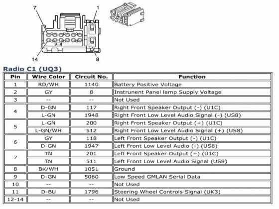
- Colors: Each wire has a specific color code, which is indicated on the diagram (e.g., RED, BLU, GRN). Matching the wire color on the diagram to the actual wire in your truck is crucial for correct connections.
- Connectors: Connectors are represented by various shapes, such as circles, squares, or rectangles, with numbers indicating the pin locations. The diagram will show where each wire connects within the connector.
- Ground Symbols: Usually represented by three horizontal lines decreasing in size, indicating a connection to the vehicle's chassis ground. A good, clean ground is essential for proper electrical function.
- Fuses: Shown as a zig-zag line enclosed in a rectangle. Fuses protect the circuit from overcurrent. The diagram will usually indicate the fuse number and amperage rating.
- Relays: Relays use a symbol that looks like a coil next to a switch. Relays are used to switch higher current circuits using a low-current control signal.
Remember, the diagram will also include abbreviations for wire colors (e.g., BK for black, WH for white) and component names. A key or legend is typically provided to explain all the symbols and abbreviations used in the diagram. Make sure to carefully review the legend before attempting to interpret the diagram.
How It Works: The Radio Circuit Flow
The basic operation of the radio circuit is relatively straightforward. Power is supplied to the head unit, typically through the ignition switch or directly from the battery (for memory functions). The head unit then processes audio signals from various sources (AM/FM tuner, CD player, auxiliary input, etc.) and amplifies them.
The amplified audio signals are then sent to the speakers through the wiring harness. The wiring harness also carries control signals that allow the head unit to communicate with other vehicle systems, such as the steering wheel controls or the OnStar module. If an amplifier is present, the head unit sends a low-level audio signal to the amplifier, which then boosts the signal and sends it to the speakers.
The CAN bus plays a crucial role in modern vehicles. It allows different modules to share information. For example, the radio might receive information from the body control module (BCM) about the vehicle speed, which can then be used to adjust the volume automatically.
Real-World Use and Basic Troubleshooting
Let's say your radio suddenly stops working. Here’s how the wiring diagram can help:
- Check the Fuses: The diagram will show you which fuse(s) protect the radio circuit. Use a multimeter to check for continuity across the fuse. A blown fuse is a common cause of radio failure.
- Inspect the Wiring Harness: Look for any signs of damage, such as frayed wires, corroded connectors, or loose connections. The diagram will help you identify the specific wires to inspect.
- Test the Power and Ground Connections: Use a multimeter to verify that the head unit is receiving power and ground. The diagram will show you which pins on the connector should have power and ground.
- Trace the Signal Path: If you suspect a problem with a specific component, such as a speaker, the diagram will help you trace the signal path from the head unit to the speaker. Use a multimeter to check for continuity and voltage along the signal path.
Example: No sound from one speaker? Consult the diagram to identify the speaker wires. Use your multimeter to check continuity of the wires to that speaker, and voltage at the speaker terminals when the radio is on.
Safety Considerations
Working with electrical systems can be dangerous if you're not careful. Here are some crucial safety tips:
- Disconnect the Battery: Always disconnect the negative battery terminal before working on the electrical system. This will prevent accidental shorts and potential shocks.
- Use Proper Tools: Use insulated tools designed for electrical work.
- Be Careful Around Airbags: The airbag system is also part of the electrical system and can be triggered accidentally. Consult your vehicle's service manual for instructions on how to disable the airbag system before working near it.
- Identify High-Current Wires: Pay special attention to the power wires, as these carry high current. Avoid accidentally shorting these wires to ground.
- Never work on the electrical system while the engine is running.
A note on aftermarket components: Be particularly cautious when installing aftermarket radios or amplifiers. Always use a wiring harness adapter designed for your vehicle to avoid cutting and splicing the factory wiring. Improper wiring can damage the vehicle's electrical system and even void your warranty.
With the 2012 Silverado radio wiring harness diagram and a little patience, you can confidently tackle almost any audio-related project on your truck. Remember to double-check your connections, use proper tools, and always prioritize safety. Now, with the knowledge from this guide, and the full diagram which is available for you to download, you're well-equipped to get started!