2012 Volvo S60 2.5l Upper Engine Ignition Coil Wiring Harness
Welcome, gearheads! Today, we're diving deep into the ignition coil wiring harness for the 2012 Volvo S60 with the 2.5L engine. Understanding this crucial component is invaluable whether you're troubleshooting a misfire, replacing a faulty coil, or simply expanding your automotive knowledge. This article will provide a detailed overview of the wiring harness, its function, and how to interpret its schematic. We’ll break down the technical jargon and provide practical tips for real-world use.
Purpose and Importance
The ignition coil wiring harness is the central nervous system for your ignition coils. It provides the electrical pathway between the engine control unit (ECU), the coils themselves, and the vehicle's power source. Without a properly functioning harness, your engine won't receive the necessary spark to ignite the air-fuel mixture, leading to misfires, poor performance, and potentially even a no-start condition. Knowing how the harness is wired and what each wire does is crucial for effective diagnosis and repair. A clear diagram is essential for any serious DIYer tackling ignition-related issues on their Volvo.
Key Specs and Main Parts
The 2012 Volvo S60 2.5L utilizes a 5-cylinder engine, meaning it has five individual ignition coils. Each coil is responsible for igniting the air-fuel mixture in its respective cylinder. The wiring harness, therefore, connects to all five coils, plus the necessary power and ground connections. Let's break down the core components:
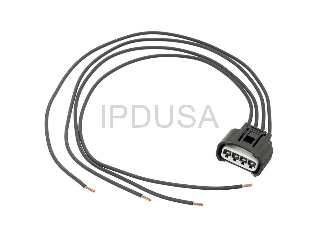
- Coil Connectors: These are the physical connectors that plug directly into the ignition coils. They usually feature three wires: power, ground, and signal from the ECU.
- Main Harness Connector: This is the point where the coil wiring harness connects to the main engine wiring harness. It provides the overall link to the ECU and the car's electrical system.
- Wiring: The individual wires within the harness, typically color-coded for identification. Each wire carries a specific signal or voltage.
- Grounding Point(s): A secure connection to the vehicle's chassis, providing a common ground for the electrical circuit. Poor grounding can cause a multitude of problems.
- Protective Sheathing/Loom: A plastic or fabric covering that protects the wires from abrasion, heat, and environmental damage.
Understanding the Wiring Diagram: Symbols, Lines, and Colors
A wiring diagram is like a roadmap for your car's electrical system. It uses standardized symbols and colors to represent different components and connections. Here's a breakdown of what you'll typically find in the ignition coil wiring diagram:
- Lines: Solid lines represent wires. Dashed lines may indicate shielding or ground connections. The thickness of the line doesn't usually indicate wire gauge, but rather visually separates different sections.
- Colors: Each wire is typically color-coded. Common colors include red (power), black (ground), and various other colors (e.g., blue, green, yellow) for signal wires. The diagram will include a legend explaining the color code. For Volvo, common colors are often abbreviated (e.g., RD for Red, BLK for Black, GRN for Green, YEL for Yellow).
- Symbols:
- Coils: Represented by a coil symbol, often with terminals labeled for power, ground, and signal.
- Connectors: Depicted as interlocking shapes, with numbers or letters indicating the pin assignments.
- Ground: Illustrated by a symbol resembling a downward-pointing pyramid, sometimes with multiple horizontal lines.
- ECU: Shown as a rectangle or square with pins labeled for input and output signals.
- Fuses: Represented by a wavy line inside a rectangle.
- Relays: Shown with a coil symbol and a set of contacts.
It's crucial to carefully study the legend accompanying the diagram to understand the specific symbols and color codes used in that particular schematic. Also, diagrams often show the wire gauge (e.g., 18 AWG, 20 AWG), which is important when replacing damaged wires. AWG stands for American Wire Gauge, and a smaller number indicates a thicker wire.
How It Works: The Ignition Coil Circuit
The ignition coil wiring harness is part of a simple but crucial circuit. Here’s a simplified explanation of how it works:
- Power Supply: The ignition coils receive power from the vehicle's electrical system, typically through a fuse and possibly a relay. This provides the initial voltage needed for the coils to operate.
- ECU Control: The ECU monitors various engine parameters, such as crankshaft position and engine load. Based on this information, the ECU sends a signal to the ignition coils to fire at the correct time.
- Coil Activation: When the ECU sends the signal, it essentially grounds the primary winding of the ignition coil. This creates a magnetic field within the coil.
- Spark Generation: When the ECU cuts the ground signal, the magnetic field collapses rapidly. This induces a high-voltage pulse in the secondary winding of the coil, which is then sent to the spark plug.
- Ground Return: The circuit is completed by a ground connection, allowing the current to flow back to the vehicle's chassis.
Real-World Use: Basic Troubleshooting Tips
If you suspect a problem with your ignition coil wiring harness, here are some basic troubleshooting steps:
- Visual Inspection: Carefully inspect the harness for any signs of damage, such as frayed wires, cracked connectors, or melted insulation. Pay close attention to areas near the exhaust manifold, where heat can cause damage.
- Continuity Testing: Use a multimeter to check the continuity of each wire in the harness. Continuity means there is an unbroken path for the current to flow. Disconnect the harness from both the coil and the ECU (or main harness) before testing. A lack of continuity indicates a broken wire.
- Voltage Testing: Use a multimeter to check for voltage at the coil connectors. With the ignition on, you should see battery voltage on the power wire. Also, check for a good ground connection.
- Resistance Testing: With the coil disconnected, use a multimeter to measure the resistance of the coil windings. Compare your readings to the manufacturer's specifications. Significantly different readings may indicate a faulty coil.
- OBD-II Codes: Use an OBD-II scanner to check for any diagnostic trouble codes (DTCs) related to the ignition system. Common codes include P0300 (Random Misfire Detected), P0301-P0305 (Cylinder Specific Misfire), and codes related to the ignition coils themselves (e.g., P0351 - Ignition Coil A Primary/Secondary Circuit Malfunction).
Important Note: When troubleshooting electrical problems, always start with the simplest and most obvious solutions, such as checking fuses and connections. Don't immediately assume the worst-case scenario.
Safety Precautions
Working with automotive electrical systems can be dangerous. Here are some important safety precautions to keep in mind:
- Disconnect the Battery: Before working on any electrical components, disconnect the negative battery terminal to prevent accidental shorts and electrical shocks.
- High Voltage: The ignition coils generate very high voltage. Never touch the coil terminals or spark plug wires while the engine is running.
- Use Proper Tools: Use insulated tools and a multimeter with appropriate voltage ratings.
- Be Careful with Fuel: When working near the fuel system, take precautions to prevent sparks, which could ignite fuel vapors.
Warning: The ignition system contains high-voltage components. Improper handling can result in serious injury or death. If you are not comfortable working on electrical systems, consult a qualified mechanic.
By understanding the ignition coil wiring harness and its function, you can effectively troubleshoot ignition-related problems and keep your 2012 Volvo S60 running smoothly. We have a detailed wiring diagram for the 2012 Volvo S60 2.5L upper engine ignition coil wiring harness available for download. Use this diagram in conjunction with the information in this article to diagnose and repair ignition problems on your Volvo.