2013 Chrysler Town And Country Fuse Box Diagram
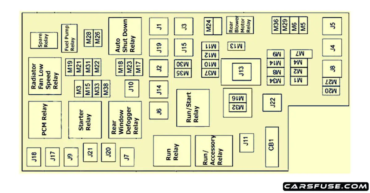
For the experienced DIYer tackling electrical issues on a 2013 Chrysler Town & Country, having a reliable fuse box diagram is absolutely essential. This isn't just a pretty picture; it's your roadmap to diagnosing and fixing problems ranging from a blown headlight to a malfunctioning power window. Think of it as the electrical schematic's simplified cousin, focusing specifically on the overcurrent protection devices—the fuses and relays—that safeguard your van's circuits. This article will delve into the specifics of the 2013 Town & Country's fuse box diagram, explaining its purpose, key components, symbols, and how to use it effectively and safely.
Purpose of the Fuse Box Diagram
The fuse box diagram serves several critical purposes:
- Troubleshooting: It allows you to quickly identify the correct fuse or relay responsible for a specific circuit. When a component fails, checking its corresponding fuse is often the first step in diagnosing the problem.
- Repair: Replacing a blown fuse with the correct amperage rating is a common repair, and the diagram tells you exactly which fuse to replace and with what rating.
- Modification: If you're adding aftermarket accessories, such as a trailer hitch wiring harness or auxiliary lighting, the diagram helps you identify unused fuse slots or circuits that can be tapped into (with appropriate caution, of course).
- Understanding the Electrical System: Studying the diagram provides a fundamental understanding of how the van's electrical system is organized and protected. You can see how different circuits are grouped and which components share the same fuse.
Key Specs and Main Parts
The 2013 Chrysler Town & Country typically has two primary fuse box locations:
- Underhood Fuse Box: This box, usually located in the engine compartment near the battery, houses fuses and relays for high-current circuits like the starter motor, alternator, headlights, and engine management systems. It’s often referred to as the Power Distribution Center (PDC).
- Interior Fuse Box: This box is typically found inside the cabin, often located under the dashboard on the driver's side. It protects circuits for interior components such as the radio, power windows, door locks, and climate control.
Within each fuse box, you'll find:
- Fuses: These are the sacrificial links in the circuit. They're designed to melt and break the circuit when the current exceeds a safe level, protecting the wiring and components from damage. Different amperage ratings (e.g., 5A, 10A, 15A, 20A, 25A, 30A, 40A) indicate the maximum current the fuse can handle before blowing.
- Relays: These are electrically operated switches that allow a low-current circuit to control a high-current circuit. For example, the headlight switch might activate a relay that then provides power to the headlights. Relays prevent high current from flowing through the switch itself, protecting it from damage.
- Fuse Puller: A small plastic tool (often integrated into the fuse box cover) used to safely remove and install fuses.
Symbols – Decoding the Diagram
Understanding the symbols on the fuse box diagram is crucial for accurate troubleshooting. Here's a breakdown:
- Lines: Solid lines typically represent the electrical circuits. Thicker lines might indicate heavier gauge wiring used for higher current circuits.
- Colors: Different colored wires often indicate different functions within a circuit. While the diagram might not explicitly show wire colors, knowing the wire color codes for Chrysler vehicles can be helpful. For example, a pink wire with a yellow tracer could be a specific signal wire for the engine control module (ECM).
- Fuse Symbols: Fuses are usually represented by a stylized "S" shape or a small rectangle with a zigzag line through it. The amperage rating is usually printed next to the fuse symbol.
- Relay Symbols: Relays are typically represented by a square with a coil symbol and a switch symbol inside. The coil represents the relay's electromagnet, and the switch represents the contacts that open and close the circuit.
- Component Icons: The diagram will often include simplified icons representing the components protected by each fuse, such as a headlight, a radio, or a power window motor.
- Text Descriptions: In addition to symbols, the diagram will include text descriptions identifying the function of each fuse and relay. For example, "Headlight - Low Beam" or "Power Window - Driver Side".
How It Works
The fuse box diagram maps the electrical protection scheme of your Town & Country. Each fuse and relay is strategically placed to protect a specific circuit or component. When a fault occurs in a circuit, such as a short circuit or an overload, the current flow increases dramatically. This excessive current causes the fuse to blow, interrupting the circuit and preventing further damage. The diagram shows you which fuse protects which circuit, allowing you to quickly isolate the problem.
Relays act as intermediaries, allowing low-current signals from switches and sensors to control high-current loads. For example, when you turn on the headlights, the headlight switch sends a low-current signal to the headlight relay. The relay then closes, providing power to the headlights. This prevents the headlight switch from having to handle the high current required by the headlights, which would eventually damage the switch.
Real-World Use – Basic Troubleshooting Tips
Here's how to use the fuse box diagram for basic troubleshooting:
- Identify the Problem: Determine which component is not working (e.g., the radio, a specific headlight, the power windows).
- Consult the Diagram: Locate the fuse box diagram (usually inside the fuse box cover or in the owner's manual). Find the fuse or relay associated with the non-functioning component.
- Inspect the Fuse: Use the fuse puller to carefully remove the fuse. Examine it closely. A blown fuse will typically have a broken filament. Sometimes, the break is obvious; other times, you'll need to hold the fuse up to the light to see it.
- Replace the Fuse: If the fuse is blown, replace it with a new fuse of the exact same amperage rating. Never use a fuse with a higher amperage rating, as this could damage the wiring or components.
- Test the Component: After replacing the fuse, test the component to see if it now works. If it does, the problem was likely a blown fuse. If the fuse blows again immediately, there is a more serious problem in the circuit (e.g., a short circuit) that needs to be investigated further.
- Check the Relay: If a relay is suspected, you can try swapping it with an identical relay from a less critical circuit (e.g., the rear window defogger relay). If the problem moves to the other circuit, the relay is faulty.
Safety – Highlight Risky Components
Working with electrical systems can be dangerous. Always follow these safety precautions:
- Disconnect the Battery: Before working on any electrical components, disconnect the negative (-) terminal of the battery. This will prevent accidental short circuits and shocks.
- Use Insulated Tools: Use tools with insulated handles to prevent electrical shock.
- Never Bypass a Fuse: Never use a piece of wire or a coin to bypass a fuse. This can cause serious damage to the wiring and components, and it can even start a fire.
- Work in a Well-Lit Area: Make sure you have adequate lighting to see what you're doing.
- Consult a Professional: If you're not comfortable working on electrical systems, consult a qualified mechanic. Some circuits, such as those related to the airbag system, can be particularly dangerous. Airbag systems store energy and can deploy unexpectedly, causing serious injury.
Remember, the fuse box diagram is your friend. By understanding how it works and following these safety guidelines, you can effectively troubleshoot and repair electrical problems on your 2013 Chrysler Town & Country.
We have the complete 2013 Chrysler Town & Country Fuse Box Diagram file available for download. You can use it alongside this article to effectively diagnose and resolve electrical issues.