2013 Dodge Challenger Trunk Fuse Box Diagram
The 2013 Dodge Challenger is a modern muscle car with a complex electrical system. Understanding the trunk fuse box diagram is crucial for any intermediate car owner, modder, or DIY mechanic who wants to perform basic troubleshooting, repairs, or modifications. This guide will walk you through the specifics of the 2013 Challenger's trunk fuse box, its components, and how to interpret the diagram effectively.
Purpose of Understanding the Trunk Fuse Box Diagram
Why bother learning about this? The trunk fuse box diagram is your roadmap to the electrical components located in the trunk of your Challenger. It allows you to:
- Troubleshoot electrical problems: Identify blown fuses that are causing issues with lights, power outlets, or other trunk-related systems.
- Perform repairs: Accurately locate and replace faulty fuses or relays.
- Add aftermarket accessories: Safely tap into the electrical system for installing things like amplifiers, subwoofers, or custom lighting. Understanding the fuse ratings and circuit protection is vital to avoid overload and electrical damage.
- Increase your overall understanding: Learning the function of each fuse and relay adds to your general car knowledge.
Key Specs and Main Parts of the 2013 Challenger Trunk Fuse Box
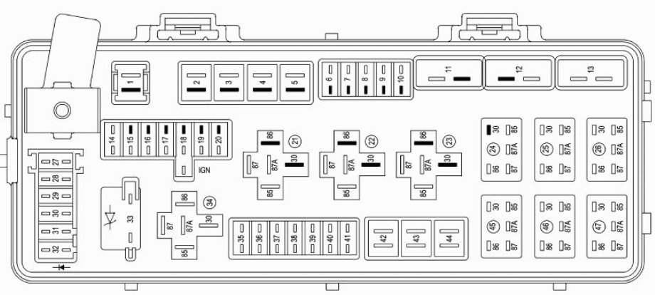
The trunk fuse box in the 2013 Dodge Challenger, officially known as the Power Distribution Center (PDC), is located in the trunk, usually behind an access panel on the driver's side. It contains an assortment of fuses and relays that protect and control various electrical circuits. Key components include:
- Fuses: These are sacrificial devices designed to break (open the circuit) when the current exceeds a safe level. This prevents damage to the wiring and components. Fuses are rated in Amperes (Amps or A), indicating the maximum current they can handle.
- Relays: Electrically operated switches that allow a low-current circuit to control a high-current circuit. Relays are commonly used to control devices like the rear defroster or amplifier power.
- Connectors: Provide connection points for wiring harnesses.
- Housing: The physical enclosure that protects the fuses, relays, and connectors from the elements.
- Diagram Label: A printed label, usually inside the fuse box cover, that identifies the function of each fuse and relay. This is what we are talking about when we say the diagram.
The fuse box typically uses a combination of different fuse types, including:
- Blade Fuses (ATO/ATC): The most common type, featuring a plastic body with exposed metal blades.
- Mini Blade Fuses: Smaller versions of blade fuses, used in circuits with lower current requirements.
Understanding the Symbols on the Fuse Box Diagram
The fuse box diagram is a symbolic representation of the electrical circuits. Understanding these symbols is essential for accurate interpretation:
- Lines: Represent wires connecting the components. The thickness of the line doesn't indicate wire gauge, but rather it is for visual clarity.
- Boxes: Represent fuses and relays. The diagram will typically label each fuse with a number and amperage rating (e.g., "F10 - 20A").
- Circles/Squares with Symbols: Represent components powered by the circuits, such as lights, motors, or electronic modules. These can be simple shapes or more detailed icons representing the specific component.
- Color Codes (on some diagrams): May indicate the color of the wire associated with a particular circuit. This is most useful when tracing wires.
- Ground Symbol: Represents the connection to the vehicle's chassis, providing a return path for the current.
The diagram will often use abbreviations to identify components. Common abbreviations include:
- IGN: Ignition
- ACC: Accessory
- PWR: Power
- DEF: Defroster
- AMP: Amplifier
How It Works: The Circuit Protection Philosophy
The fuse box serves as a central point for distributing power and protecting the electrical system. Each circuit is designed with a specific fuse rating that is appropriate for the load it carries. When an overload occurs (e.g., a short circuit), the fuse blows, breaking the circuit and preventing damage to the wiring and components. The relay allows for lower current switches and controls to safely activate higher current systems, ensuring driver control without risking damage to the low current control circuit.
Imagine the circuit as a water pipe. The fuse is a narrow section of that pipe. If too much water pressure (current) tries to flow through, the narrow section breaks, stopping the flow and preventing damage to the rest of the pipe (the wiring and electrical components).
Real-World Use: Basic Troubleshooting Tips
Here's how to use the trunk fuse box diagram for basic troubleshooting:
- Identify the Problem: Determine which electrical component is not working (e.g., the trunk light).
- Consult the Diagram: Locate the fuse associated with the non-functional component in the trunk fuse box diagram.
- Inspect the Fuse: Visually inspect the fuse. A blown fuse will typically have a broken filament or a darkened appearance.
- Test the Fuse: Use a multimeter set to continuity mode to test the fuse. A good fuse will have continuity (the multimeter will beep). A blown fuse will not have continuity.
- Replace the Fuse: Replace the blown fuse with a new fuse of the same amperage rating. Using a higher amperage fuse can overload the circuit and cause damage or even a fire.
- Test the Component: After replacing the fuse, test the component to see if it is now working. If the fuse blows again immediately, there is likely a short circuit in the wiring or the component itself. Further investigation is needed.
Safety Precautions
Working with electrical systems can be dangerous. Take the following precautions:
- Disconnect the Battery: Before working on the fuse box, disconnect the negative battery terminal to prevent accidental short circuits. Use proper tools and wear insulated gloves if possible.
- Never Replace a Fuse with a Higher Amperage: This can overload the circuit and cause damage or fire.
- Avoid Working in Wet Conditions: Water and electricity are a dangerous combination.
- Be Cautious Around Relays: Relays can sometimes contain capacitors that can store a charge even after the battery is disconnected. Discharge them before handling.
- High-Current Circuits: Be extra cautious when working with circuits that handle high current, such as the rear defroster or amplifier power. These circuits can deliver a significant shock.
Disclaimer: This guide provides general information and troubleshooting tips. Always consult the official 2013 Dodge Challenger service manual for specific procedures and specifications.
We have a copy of the 2013 Dodge Challenger Trunk Fuse Box Diagram file available for download. This diagram will provide a visual aid while doing troubleshooting.