2013 Dodge Charger Front Suspension Diagram
The 2013 Dodge Charger, known for its bold styling and performance, relies on a well-engineered front suspension system for handling and ride comfort. Understanding this system is crucial for anyone looking to perform maintenance, repairs, or even modifications. This article provides a detailed look at the 2013 Dodge Charger's front suspension diagram, breaking down its components, functions, and real-world applications. We'll cover everything from basic terminology to troubleshooting tips, ensuring you have a solid understanding of this critical system.
Purpose of the Front Suspension Diagram
A front suspension diagram is more than just a pretty picture; it's an essential tool for several reasons:
- Repair and Maintenance: It allows you to identify and locate specific components for replacement or repair. Without a diagram, diagnosing issues and ordering the correct parts becomes significantly more challenging.
- Troubleshooting: The diagram helps you trace the connections and relationships between different components, aiding in the diagnosis of suspension-related problems like clunking noises, poor handling, or uneven tire wear.
- Modification and Upgrades: For those looking to modify their Charger's suspension, a diagram is essential for understanding how different aftermarket parts will integrate with the existing system.
- Learning and Understanding: Even if you're not planning on wrenching on your car yourself, understanding the diagram gives you a deeper appreciation for the engineering that goes into your vehicle.
Key Specs and Main Parts
The 2013 Dodge Charger, in most of its trim levels, utilizes an independent front suspension system, typically a short-and-long arm (SLA) design, also sometimes referred to as a double wishbone suspension. This design offers excellent handling characteristics and ride quality. Here's a breakdown of the key components:
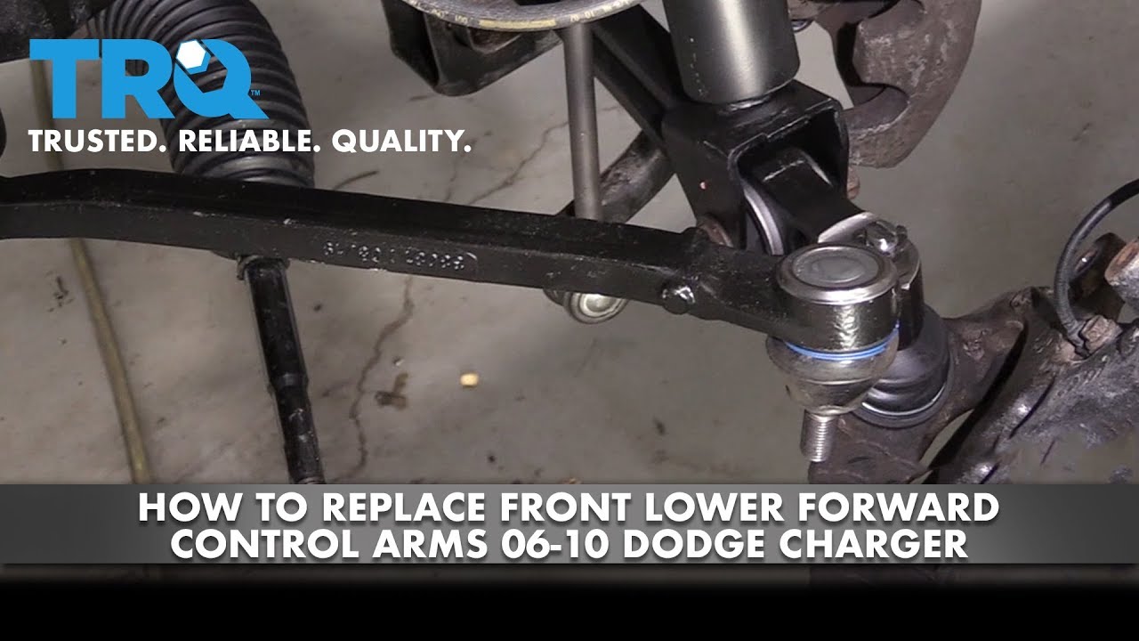
- Upper and Lower Control Arms: These arms connect the wheel hub to the vehicle's frame. The upper and lower control arms pivot allowing the wheel to move up and down, while maintaining a relatively constant camber angle. This is crucial for optimal tire contact with the road.
- Coil Springs: The coil springs are the primary load-bearing components of the suspension. They absorb impacts from the road, providing a smoother ride.
- Shock Absorbers (Dampers): These control the oscillations of the coil springs, preventing the car from bouncing excessively. They dampen the spring's movement, providing a controlled and comfortable ride.
- Steering Knuckle (Spindle): This component connects the control arms, wheel hub, and steering components. It allows the wheels to pivot for steering.
- Wheel Hub and Bearings: The wheel hub is the central part of the wheel assembly, and the bearings allow the wheel to rotate freely.
- Sway Bar (Stabilizer Bar): This bar connects the left and right sides of the suspension. It resists body roll during cornering, improving handling stability.
- Sway Bar End Links: These connect the sway bar to the control arms or struts.
- Ball Joints: These are spherical bearings that allow the control arms and steering knuckle to move freely while maintaining a secure connection.
- Tie Rods (Inner and Outer): These connect the steering rack to the steering knuckle, transmitting steering input to the wheels.
- Strut Tower (Mount): The upper mounting point for the suspension assembly.
Understanding Diagram Symbols
Interpreting the diagram requires understanding the symbols used. While specific diagrams may vary slightly, here are some common conventions:
- Lines: Lines represent connections between components. Thicker lines often indicate structural components, while thinner lines might represent hydraulic or electrical connections related to optional adaptive suspension systems (if equipped).
- Hatching: Hatching or cross-hatching typically indicates a cutaway view, allowing you to see internal details of a component.
- Arrows: Arrows often indicate the direction of movement or force. For example, an arrow might show the direction of spring compression or the direction of steering input.
- Numbers and Letters: These are used to identify specific components and may correspond to a parts list or repair manual.
- Colors: Color-coding can be used to distinguish different systems or materials. For example, red might indicate hydraulic lines, while blue might indicate electrical wiring.
How It Works
The 2013 Dodge Charger's front suspension is designed to provide a balance of ride comfort and handling performance. Here's a simplified explanation of how it works:
- When the car encounters a bump, the wheel moves upwards.
- This upward movement compresses the coil spring, absorbing the impact energy.
- The shock absorber dampens the oscillations of the spring, preventing excessive bouncing.
- The control arms allow the wheel to move up and down while maintaining a consistent camber angle, ensuring optimal tire contact with the road.
- The sway bar resists body roll during cornering, improving stability and handling. When one wheel begins to lift, the sway bar transfers some of that force to the other wheel keeping them planted firmly on the road.
- Steering input from the steering wheel is transmitted through the steering rack and tie rods to the steering knuckles, causing the wheels to turn.
Real-World Use: Basic Troubleshooting
The front suspension is subject to significant stress and wear, leading to various problems. Here are some common issues and how the diagram can help:
- Clunking Noises: These noises often indicate worn ball joints, tie rod ends, sway bar end links, or bushings. Use the diagram to locate these components and visually inspect them for wear or damage.
- Poor Handling: This could be caused by worn shock absorbers, broken springs, or loose suspension components. The diagram helps you identify these parts and assess their condition.
- Uneven Tire Wear: This can result from misaligned suspension components, worn ball joints, or damaged control arms. The diagram helps you understand the geometry of the suspension and identify potential sources of misalignment.
- Vibrations: Vibrations can stem from damaged wheel bearings, worn ball joints or damaged struts. Consult the diagram and start from the wheel hub and up.
Safety Considerations
Working on the front suspension can be dangerous due to the high forces involved. Here are some critical safety precautions:
- Spring Compression: Coil springs store a tremendous amount of energy, and improper handling can lead to serious injury or even death. Always use a spring compressor specifically designed for automotive use and follow the manufacturer's instructions carefully. If you are uncomfortable with this process, have a professional mechanic perform the work.
- Vehicle Support: Never work under a vehicle supported only by a jack. Always use jack stands placed on designated jacking points.
- Torque Specifications: Always tighten fasteners to the correct torque specifications. Over-tightening can damage components, while under-tightening can lead to loosening and failure. Consult a repair manual for the correct torque values.
- Eye Protection: Wear safety glasses to protect your eyes from flying debris.
In summary, understanding the 2013 Dodge Charger front suspension diagram is vital for diagnosing problems, performing repairs, and making informed decisions about modifications. By understanding the components, their functions, and potential failure points, you can keep your Charger running smoothly and safely.
We have the detailed 2013 Dodge Charger front suspension diagram available for download. It includes a complete parts list and detailed views, which can be a valuable resource for your projects.