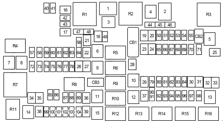
2013 Dodge Ram 1500 Fuse Box Diagram
Hey there, DIY mechanics and Ram enthusiasts! Today, we're diving deep into the heart of your 2013 Dodge Ram 1500's electrical system: the fuse box diagram. This seemingly simple chart is your roadmap to troubleshooting electrical issues, safely adding aftermarket accessories, and understanding the intricate web that powers your truck. We have the 2013 Dodge Ram 1500 Fuse Box Diagram readily available for download, which you can use alongside this guide.
Purpose: Why You Need This Diagram
Let's be honest, electrical problems can be a nightmare. A seemingly minor short circuit can disable crucial systems, leaving you stranded. That's where the fuse box diagram comes in. It's essential for:
- Troubleshooting Electrical Faults: Identifying which fuse protects a specific circuit helps you pinpoint the source of the problem faster, whether it's a blown fuse, a wiring issue, or a faulty component.
- Adding Aftermarket Accessories: Planning to install a new stereo, auxiliary lights, or a trailer brake controller? Knowing which circuits are available and their amperage ratings ensures you don't overload the system and potentially damage your truck.
- Understanding Your Vehicle's Electrical System: Even if you're not experiencing problems, studying the fuse box diagram provides valuable insights into how the various systems of your Ram 1500 are interconnected.
- Preventing Costly Repairs: Before taking your truck to a mechanic for electrical repairs, understanding the fuse layout allows you to inspect the fuses, possibly resolving the issue quickly and saving you money.
Key Specs and Main Parts
The 2013 Ram 1500 typically has two primary fuse boxes:
- Power Distribution Center (PDC) - Under the Hood: This is the main fuse box, housing larger fuses and relays responsible for high-current circuits like the starter motor, alternator, and air conditioning compressor. You'll often find it near the battery.
- Interior Fuse Box - Instrument Panel (IP): Located inside the cabin, often on the driver's side behind a panel, this fuse box protects lower-current circuits like the radio, power windows, and interior lights.
Within these fuse boxes, you'll find:
- Fuses: These are sacrificial devices designed to protect circuits from overcurrent. They contain a thin wire that melts and breaks the circuit when excessive current flows through it. Fuses are rated in amperes (amps), indicating the amount of current they can handle before blowing. Common fuse types include blade fuses (ATO/ATC), mini-blade fuses, and cartridge fuses.
- Relays: Electrically operated switches that allow a low-current circuit to control a high-current circuit. Relays are used to control devices like headlights, fuel pumps, and horns.
- Circuit Breakers: Resettable devices that protect circuits from overcurrent. Unlike fuses, they don't need to be replaced after tripping. Instead, they can be reset manually or automatically.
Symbols and Diagram Interpretation
Fuse box diagrams use symbols and abbreviations to represent different components and circuit paths. Understanding these is crucial for accurate diagnosis.
- Lines: Solid lines typically represent the wiring, while dashed lines may indicate ground connections or control circuits.
- Colors: Wires are often color-coded, and the diagram may indicate these colors (e.g., RED, BLU, GRN). Using a wiring diagram in conjunction with the fuse box diagram can be helpful.
- Icons:
- A zig-zag line inside a rectangle usually denotes a resistor or a load.
- A coil symbol represents a relay.
- A circle with a letter inside often indicates a specific connector.
- Amperage Ratings: Each fuse location is labeled with its amperage rating (e.g., 10A, 20A, 30A). This is the maximum current the fuse can handle.
- Circuit Descriptions: The diagram provides a brief description of the circuit each fuse protects (e.g., "Radio," "Headlights," "Power Windows").
How It Works: The Electrical Flow
The electrical system of your Ram 1500 is a complex network, but the basic principle is simple: electricity flows from the battery, through the wiring, to the various components that use it. The fuse box is a critical point in this network, providing protection against overcurrents. Here's a simplified breakdown:
- The battery provides the initial electrical power.
- The power travels through the main wiring harness to the Power Distribution Center (PDC).
- Within the PDC, fuses protect individual circuits. If a circuit draws too much current (due to a short circuit or overload), the fuse blows, interrupting the flow of electricity and preventing damage to the wiring and components.
- From the PDC, power is distributed to various systems throughout the vehicle.
- Some circuits are further protected by fuses in the Interior Fuse Box (IP).
- Relays are used to control high-current devices, allowing them to be switched on and off by a low-current signal from a switch or computer.
Real-World Use: Basic Troubleshooting Tips
Okay, so you've got the diagram. Now what? Here are some basic troubleshooting steps:
- Identify the Problem: What's not working? Be specific (e.g., "The power windows on the driver's side aren't working").
- Consult the Diagram: Locate the fuse associated with the affected system on the fuse box diagram.
- Inspect the Fuse: Visually inspect the fuse. If the wire inside is broken or blackened, the fuse is blown. You can also use a multimeter to test the fuse for continuity. Set your multimeter to continuity mode (it usually has a sound indicator). Place the probes on each end of the fuse. If you hear a beep, the fuse is good; if not, it's blown.
- Replace the Fuse: Replace the blown fuse with a new fuse of the exact same amperage rating. Using a higher-rated fuse can damage the wiring and components.
- Test the System: After replacing the fuse, test the system to see if it's working.
- If the Fuse Blows Again: If the new fuse blows immediately or shortly after being replaced, there's likely a short circuit or overload in the circuit. Further diagnostics are needed, such as checking the wiring for damage or testing the components connected to the circuit. This is where a wiring diagram becomes invaluable.
Example: Your radio suddenly stops working. You check the fuse box diagram and find that fuse #25 (let's say) in the Interior Fuse Box is labeled "Radio - 15A." You visually inspect the fuse and see that it's blown. You replace it with a new 15A fuse, and the radio starts working again. Problem solved!
Safety: Handle with Care
Working with automotive electrical systems can be dangerous. Here are some crucial safety precautions:
- Disconnect the Battery: Before working on any electrical system, disconnect the negative (-) battery cable to prevent accidental shorts and electric shocks.
- Use Insulated Tools: Use tools with insulated handles to minimize the risk of electric shock.
- Never Bypass Fuses: Never replace a blown fuse with a wire or any other conductive material. This bypasses the circuit protection and can lead to serious damage or fire.
- Be Careful with Relays: Relays can get hot when energized. Allow them to cool before handling them.
- Work in a Well-Ventilated Area: Batteries can produce hydrogen gas, which is flammable. Work in a well-ventilated area to prevent the buildup of gas.
High-Risk Components: Pay special attention when working near the alternator, starter motor, and airbags. These components operate at high voltages or currents and can be dangerous if mishandled. If you're not comfortable working on these systems, consult a qualified mechanic.
We have the full 2013 Dodge Ram 1500 Fuse Box Diagram file ready for you to download. Remember, this guide is for informational purposes only. Always consult a qualified mechanic if you're unsure about any electrical repair or modification.