
2013 Ford Edge Rear Suspension Diagram
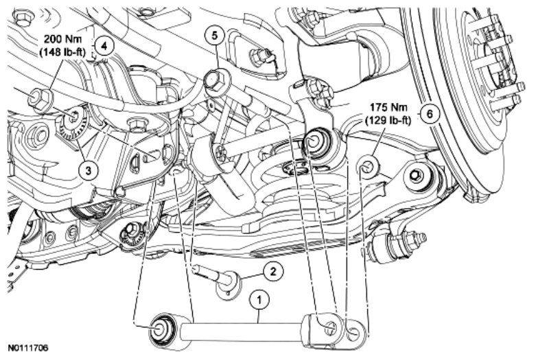
Welcome, fellow gearheads! Today, we're diving deep into the rear suspension system of the 2013 Ford Edge. This isn't just some academic exercise; understanding your Edge's rear suspension empowers you to perform repairs, diagnose problems, and even explore performance modifications with confidence. Think of this as your comprehensive guide, breaking down the complexities into manageable chunks.
Purpose of a Rear Suspension Diagram
Why bother understanding a diagram? Well, imagine trying to fix your computer without knowing what the motherboard looks like. A rear suspension diagram is essentially a roadmap of the entire system. It helps you:
- Identify Components: Quickly locate and name each part.
- Understand Relationships: See how components interact and affect each other.
- Troubleshoot Issues: Pinpoint the source of a problem based on symptoms.
- Plan Repairs: Order the correct parts and understand the disassembly/reassembly process.
- Facilitate Modifications: Design and implement suspension upgrades intelligently.
Without a good understanding, you’re essentially working blind. This guide and the associated diagram (which you can download – more on that later) will illuminate the path to a smoother, safer, and more enjoyable driving experience.
Key Specs and Main Parts of the 2013 Ford Edge Rear Suspension
The 2013 Ford Edge utilizes an independent rear suspension (IRS) system, specifically a multi-link design. This type of suspension offers superior handling and ride comfort compared to older, simpler designs like solid axles. Let's break down the key components:
- Lower Control Arm: Also known as the transverse link. This is a primary structural member connecting the wheel hub to the vehicle's chassis. It controls wheel movement in a vertical plane and helps maintain proper camber.
- Upper Control Arm (Camber Link): Another crucial link connecting the hub to the chassis. Its primary function is to control the camber angle (the angle of the wheel relative to the vertical axis). Adjustments to this arm can be made to fine-tune the vehicle's handling.
- Toe Link: As the name suggests, this link controls the toe angle (the angle of the wheel relative to the vehicle's longitudinal axis). Proper toe is essential for straight-line stability and tire wear.
- Trailing Arm: A longitudinal arm that helps control fore-aft wheel movement and braking forces. It pivots at the chassis and connects to the hub carrier.
- Coil Spring: The primary component responsible for supporting the vehicle's weight and absorbing bumps. The spring rate (stiffness) determines the ride quality.
- Shock Absorber (Damper): Works in conjunction with the coil spring to dampen oscillations and prevent the vehicle from bouncing excessively. A worn shock absorber will lead to a bouncy, unstable ride.
- Wheel Hub/Bearing Assembly: The rotating component that the wheel attaches to. It contains the wheel bearing, which allows the wheel to spin freely. A worn bearing will often produce a grinding or humming noise.
- Stabilizer Bar (Sway Bar): Connects the left and right sides of the suspension to reduce body roll during cornering. It improves handling and stability.
- Subframe: A structural frame that supports the entire rear suspension assembly and isolates it from the vehicle's body, reducing noise and vibration.
Decoding the Diagram: Symbols and Conventions
The diagram you'll download uses standard engineering conventions. Here's a breakdown of what you might encounter:
- Solid Lines: Typically represent physical components, like control arms or the subframe. Thicker lines often indicate larger, more structural parts.
- Dashed Lines: May represent hidden components or lines of action (forces).
- Arrows: Indicate direction of movement, forces, or fluid flow (if hydraulic components were involved).
- Callouts/Labels: Each component will be clearly labeled with its name and often a reference number. This number is crucial for ordering the correct replacement parts.
- Hatching/Cross-Hatching: Often used to indicate sections of a component or areas where two parts are joined together.
- Torque Specifications: Critical bolts and fasteners will often have torque specifications listed near them, usually in Newton-meters (Nm) or foot-pounds (ft-lbs). Always use a torque wrench and adhere to these specifications!
- Color Coding (If Present): Some diagrams use color to differentiate between different types of components (e.g., suspension components in one color, brake components in another).
Remember to pay close attention to the legend or key provided with the diagram, as it will explain any specific symbols or conventions used.
How the 2013 Ford Edge Rear Suspension Works
The multi-link IRS system is designed to provide independent control over each wheel's movement. When one wheel encounters a bump, the suspension on that side reacts independently of the other side. This helps to maintain tire contact with the road and improve ride comfort and handling. Here's a simplified explanation:
- Wheel Movement: As the wheel moves up and down in response to road irregularities, the control arms pivot on their bushings.
- Spring Compression/Extension: The coil spring compresses to absorb the impact, storing energy. As the spring releases, it extends, pushing the wheel back down.
- Damping: The shock absorber controls the rate of compression and extension of the spring, preventing excessive bouncing and maintaining stability.
- Stabilizer Bar Action: During cornering, the stabilizer bar resists body roll by transferring force from the outside wheel to the inside wheel, helping to keep the vehicle level.
- Alignment Control: The upper control arm and toe link work together to maintain proper wheel alignment (camber and toe) throughout the suspension's range of motion. This ensures optimal tire wear and handling characteristics.
The bushings in the control arms play a vital role in absorbing vibrations and allowing the suspension to move smoothly. Worn bushings can lead to noise, vibration, and poor handling.
Real-World Use: Basic Troubleshooting Tips
Now, let's get practical. Here are some common rear suspension issues and how the diagram can help you diagnose them:
- Clunking Noise: Could indicate worn bushings in the control arms, a loose shock absorber, or a broken spring. Use the diagram to locate these components and inspect them for damage or excessive play.
- Bouncy Ride: Likely caused by worn shock absorbers. The diagram will show you the location and mounting points of the shocks.
- Uneven Tire Wear: Often a sign of misaligned wheels. The diagram highlights the camber and toe adjustment points on the upper control arm and toe link. You'll need specialized alignment equipment to correct this issue.
- Vehicle Pulling to One Side: Can be caused by a bent control arm, a seized bushing, or uneven tire pressure. Inspect the control arms for damage using the diagram as a reference.
- Excessive Body Roll: May indicate a broken or disconnected stabilizer bar. The diagram will show you how the stabilizer bar connects to the suspension.
Always remember that diagnosing suspension problems can be tricky, and sometimes it requires a trained eye and specialized equipment. If you're unsure, consult a qualified mechanic.
Safety Considerations
Working on suspension systems can be dangerous due to the presence of compressed springs and potentially corroded fasteners. Here are some key safety precautions:
- Spring Compression: Never attempt to disassemble a coil spring without a proper spring compressor. A compressed spring stores a tremendous amount of energy and can cause serious injury if it suddenly releases.
- Vehicle Support: Always use jack stands to support the vehicle before working underneath it. Never rely solely on a jack.
- Fastener Corrosion: Corroded fasteners can be difficult to remove and may break, leading to injury or damage. Use penetrating oil and appropriate tools to loosen stubborn fasteners.
- Brake Lines: Be extremely careful when working near brake lines. Damaging a brake line can lead to a loss of braking power.
- Eye Protection: Always wear safety glasses to protect your eyes from debris.
- Disconnect Battery: It's a good idea to disconnect the negative battery terminal before starting any work on your vehicle to prevent accidental electrical shorts.
The 2013 Ford Edge rear suspension is a complex system, but with the right knowledge and tools, you can confidently diagnose and repair many common issues. Remember to always prioritize safety and consult a qualified mechanic if you're unsure about anything. We have the detailed diagram available for download. This will be an invaluable resource as you delve into the intricacies of your Edge's rear suspension!