2013 Ford F150 Blower Motor Resistor Wiring Diagram
So, you're diving into the climate control system of your 2013 Ford F-150? Smart move. Understanding the blower motor resistor and its wiring is key for tackling issues like a blower motor that only works on certain speeds, or not at all. This isn't just about comfort; it's about safety too, as a malfunctioning HVAC system can impact visibility by fogging up windows. This article will guide you through the wiring diagram, helping you diagnose problems and make informed repairs. We'll approach it like a seasoned mechanic walking you through the steps, ensuring you understand the "why" behind the "how".
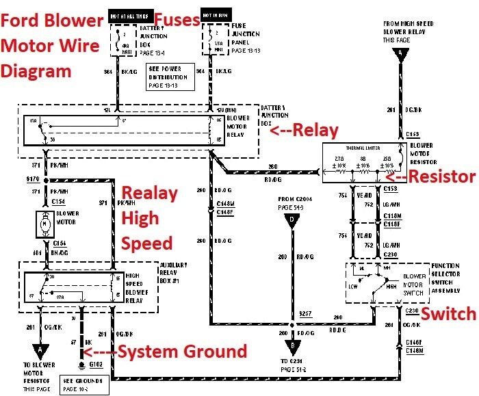
Purpose of the Blower Motor Resistor Wiring Diagram
Why bother with a wiring diagram? Several reasons. First, it's invaluable for troubleshooting. When your blower motor isn't behaving, the diagram allows you to trace the circuit, identifying potential points of failure like broken wires, corroded connectors, or a faulty resistor itself. Second, it's crucial for repairs and component replacement. Ensuring you're connecting things correctly after replacing the resistor or motor is paramount. Finally, understanding the diagram enhances your overall understanding of the vehicle's electrical system, making you a more confident and capable DIYer.
Key Specs and Main Parts
Let's break down the key components involved in the blower motor circuit of your 2013 F-150:
- Blower Motor: This is the electric motor that spins the fan, forcing air through the HVAC system and into the cabin. It's a relatively high-current device.
- Blower Motor Resistor: This is the critical component we're focusing on. The resistor pack consists of several resistors of varying values. These resistors drop the voltage to the blower motor, allowing you to control its speed. Each resistor corresponds to a different speed setting on your climate control panel. Without the resistor, the blower motor would only run at full speed.
- Blower Motor Control Switch (or Module): This is the switch on your dashboard that allows you to select the desired blower speed. In some higher-trim models, this may be a more complex electronic module rather than a simple switch.
- Fuse: A crucial safety device. The fuse protects the circuit from overcurrent, preventing damage to the wiring and components in case of a short circuit. Its value (e.g., 25A, 30A) is vital for correct operation.
- Relay: In some F-150 configurations, a relay is used to switch the high-speed setting on or off, as the high-speed setting typically bypasses the resistor pack entirely.
- Wiring Harness and Connectors: The arteries of the system, carrying the electrical current between the components.
Understanding Wiring Diagram Symbols
Wiring diagrams use standardized symbols to represent electrical components and connections. Here's a breakdown of the common symbols you'll encounter in the 2013 F-150 blower motor resistor wiring diagram:
- Solid Lines: Represent wires. The thickness of the line *doesn't* typically indicate wire gauge, so rely on the diagram's wire gauge specifications.
- Dashed Lines: Often indicate shielded wiring or connections to ground.
- Circles: Can represent connectors, junctions, or components, depending on what is inside.
- Resistor Symbol (Zigzag Line): Indicates a resistor. In the blower motor resistor diagram, you'll see several of these, each with a different resistance value.
- Ground Symbol (Series of Decreasing Lines): Indicates a connection to ground (the vehicle's chassis). Ground is essential for completing the circuit.
- Fuse Symbol (Rectangle with a Serpentine Line): Represents a fuse. The diagram will often indicate the fuse's amperage rating.
- Relay Symbol (Coil and Switch): Represents a relay, a remotely controlled switch.
Color Coding: Wire colors are usually indicated by abbreviations (e.g., RD for Red, BK for Black, WH for White). Knowing the wire colors helps you trace the circuit in the real world. The diagram will contain a color key to decipher these abbreviations.
How the Blower Motor Circuit Works
The blower motor circuit is relatively simple. Power flows from the battery, through a fuse, and then to the blower motor control switch (or module). When you select a blower speed, the switch directs current to a specific resistor in the resistor pack. The resistor reduces the voltage supplied to the blower motor. The higher the resistance, the lower the voltage, and the slower the blower motor spins. On the highest speed setting, the resistor pack is typically bypassed entirely, sending full voltage directly to the blower motor for maximum airflow.
Consider this example: Low speed might use a resistor that drops the voltage to 6 volts, medium speed might use a resistor that drops the voltage to 9 volts, and high speed bypasses the resistor entirely, supplying the full 12 volts. This voltage drop is what gives you the varying speeds.
Real-World Use: Basic Troubleshooting Tips
Here are some common blower motor problems and how the wiring diagram can help you diagnose them:
- Blower Motor Doesn't Work at All: Check the fuse first. If the fuse is blown, replace it with one of the *correct* amperage rating. If the new fuse blows immediately, there's likely a short circuit in the wiring or the blower motor itself. Use the wiring diagram to trace the circuit and identify the short. Also verify the ground connections.
- Blower Motor Only Works on High Speed: This is a classic symptom of a failed blower motor resistor. The high-speed setting bypasses the resistor pack, so if that's the only speed that works, the resistors are likely the culprit. The wiring diagram will show you how to locate the resistor pack and test its individual resistors with a multimeter.
- Blower Motor Works on Some Speeds But Not Others: This indicates that one or more of the resistors in the resistor pack has failed. Again, the wiring diagram is essential for locating and testing the resistors.
- Erratic Blower Motor Operation: This could be caused by loose connectors, corroded wiring, or a failing blower motor control switch. Use the wiring diagram to inspect the connectors and wiring in the circuit.
Safety Considerations
Disconnect the Battery: Always disconnect the negative battery terminal before working on any electrical system in your vehicle. This prevents accidental shorts and electrical shocks.
Fuses: Never replace a fuse with one of a higher amperage rating. Doing so can overload the circuit and cause a fire.
Blower Motor Resistor: These resistors can get very hot during operation. Allow them to cool down before handling them.
High-Current Circuits: The blower motor circuit is a relatively high-current circuit. Use caution when working on it, and ensure that all connections are secure.
Airbag Systems: Be extremely cautious when working near airbag systems. Consult your vehicle's service manual for proper procedures to avoid accidental deployment.
Disclaimer: Working on automotive electrical systems can be dangerous. If you are not comfortable working on electrical systems, consult a qualified mechanic.
Remember to always consult your specific vehicle's repair manual for the most accurate and up-to-date information.
Now that you have a solid understanding of the 2013 Ford F-150 blower motor resistor wiring diagram, you're well-equipped to troubleshoot and repair your vehicle's climate control system. Remember to take your time, work carefully, and prioritize safety.
We have the complete wiring diagram readily available for download. It contains detailed schematics, component locations, and wire color codes specific to your 2013 F-150. Use it wisely!