2013 Ford F150 Radio Wiring Harness Diagram
Alright, let's dive into the 2013 Ford F150 radio wiring harness diagram. This is your roadmap to understanding the intricate electrical connections that power your truck's audio system. Whether you're upgrading your head unit, diagnosing a speaker issue, or simply trying to understand how everything is connected, having a clear understanding of this diagram is invaluable. It’s your key to avoiding costly mistakes and potentially frying components.
Purpose of the Wiring Harness Diagram
This diagram isn’t just a pretty picture; it’s a critical tool for several scenarios:
- Head Unit Replacement/Upgrade: Swapping out your factory radio for a new aftermarket unit requires precise wiring. The diagram ensures you connect the correct wires, preventing damage and ensuring proper functionality.
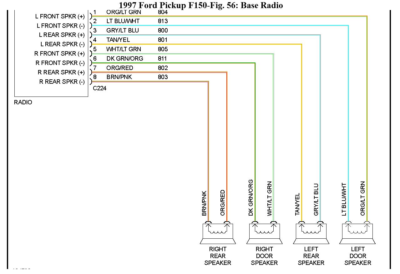
- Speaker Installation: Upgrading or replacing speakers often involves tapping into existing wiring. The diagram helps you identify the correct speaker wires (positive and negative) for each speaker location.
- Troubleshooting Audio Problems: If you're experiencing issues like no sound, distorted audio, or a dead radio, the diagram helps you trace the wiring and identify potential faults (shorts, opens, etc.).
- Adding Amplifiers or Other Audio Components: Integrating amplifiers, subwoofers, or other audio enhancements requires understanding the factory wiring to properly tap into the system.
- Learning About Your Truck's Electrical System: Even if you're not actively working on your audio system, studying the diagram can give you a deeper understanding of how the electrical components of your F150 are interconnected.
Key Specs and Main Parts of the Radio Wiring Harness
The 2013 F150 radio wiring harness connects the head unit to various components, including:
- Power Supply: Provides the necessary voltage (typically 12V DC) for the radio to operate.
- Ground: Completes the electrical circuit, providing a return path for the current.
- Speakers: Sends the amplified audio signal to the speakers.
- Antenna: Receives radio signals.
- Accessory Power: Turns the radio on and off with the ignition.
- Illumination: Dims the radio display when the headlights are turned on.
- Steering Wheel Controls: Allows you to control the radio from the steering wheel (if equipped).
- Vehicle Speed Sensor (VSS): Provides speed information for features like speed-sensitive volume control (if equipped).
- Factory Amplifier (if equipped): In some models, a separate amplifier powers the speakers. The harness connects to this amplifier.
- SYNC module (if equipped): Integrates Ford's SYNC system.
The harness itself consists of multiple wires, each with a specific color and function, terminating in connectors that plug into the back of the radio and other components. Connector types can vary depending on the trim level and options your F150 has.
Understanding the Symbols: Lines, Colors, and Icons
The wiring diagram uses a standardized set of symbols to represent different components and connections. Understanding these symbols is crucial for interpreting the diagram correctly.
- Lines: Represent wires. The thickness of the line may indicate the wire gauge (thicker lines typically indicate larger gauge wires that can carry more current).
- Colors: Each wire has a specific color code, which is indicated on the diagram. Common colors include red (power), black (ground), white (speaker), and various other colors for different functions. These colors can slightly differ between model years, but are mostly standardized within the Ford Eco-system.
- Symbols for Components: The diagram uses specific symbols to represent components such as resistors (zigzag line), capacitors (two parallel lines), diodes (triangle pointing to a line), and ground (series of lines getting shorter).
- Connectors: Represented by boxes or circles, indicating where wires connect to other components or harnesses. Connector pin numbers are often labeled to identify the specific wire within the connector.
- Splices: Show where multiple wires are joined together.
- Fuses: Fuses, crucial components for circuit protection, are also represented.
Pay close attention to the color codes. They are your primary key to identifying the correct wires. However, always double-check with a multimeter to confirm the function of a wire before making any connections. Color codes can sometimes vary slightly depending on the specific trim level and options of your F150.
How It Works: Tracing the Signal Path
The wiring diagram essentially maps the flow of electricity and audio signals within the system. Here's a simplified overview of how it works:
- Power Source: The radio receives power from the vehicle's battery through the power and ground wires. The ignition wire provides power only when the ignition is turned on.
- Signal Input: The radio receives audio signals from various sources, such as the antenna (for AM/FM radio), CD player (if equipped), or external devices connected through auxiliary inputs or Bluetooth.
- Signal Processing: The radio's internal circuitry processes these signals, amplifies them, and adjusts the tone (bass, treble, etc.).
- Signal Output: The amplified audio signals are then sent to the speakers through the speaker wires. Each speaker has a positive and negative wire.
- Control Signals: The radio also receives control signals from the steering wheel controls, vehicle speed sensor, and other systems. These signals allow you to control the radio's functions and adjust settings based on vehicle speed.
By tracing the signal path on the diagram, you can understand how each component contributes to the overall operation of the audio system. For example, if you're experiencing a problem with the front right speaker, you can trace the wiring from the radio to the speaker to identify any potential breaks or shorts in the circuit.
Real-World Use: Basic Troubleshooting Tips
Here are some basic troubleshooting scenarios and how the wiring diagram can help:
- No Power to Radio: Check the power and ground wires. Use a multimeter to verify that the power wire has 12V DC and the ground wire has continuity to ground. Also, check the fuse for the radio in the fuse box.
- No Sound from Speakers: Check the speaker wires. Use a multimeter to verify that there is continuity between the radio and the speaker. If you suspect a short, disconnect the speaker and measure the resistance between the speaker wires and ground. A low resistance indicates a short.
- Distorted Sound: Could be a faulty speaker, amplifier (if equipped), or wiring issue. Check the speaker wires for any damage or corrosion. Try swapping speakers to see if the problem moves with the speaker.
- Steering Wheel Controls Not Working: Check the wiring for the steering wheel controls. Verify that the wires are properly connected to the radio and that there are no breaks in the circuit.
Always remember to disconnect the battery before working on any electrical components to prevent accidental shorts or shocks.
Safety: Highlighting Risky Components
Working with automotive electrical systems involves inherent risks. Here are a few key safety considerations:
- Battery: The battery is a powerful source of energy. Always disconnect the negative terminal before working on any electrical components.
- Airbag System: The airbag system is a sensitive and potentially dangerous system. Avoid working near airbag components unless you have proper training and knowledge. Disconnecting or tampering with airbag wiring can cause accidental deployment or malfunction.
- Fuses: Never replace a fuse with a higher amperage fuse. This can overload the circuit and cause a fire.
- Wiring: Be careful when cutting or splicing wires. Use proper crimping tools and connectors to ensure secure and reliable connections. Poorly made connections can cause shorts, opens, and other electrical problems.
- Capacitors: Capacitors can store electrical charge even after the power is disconnected. Be careful when handling capacitors, especially in amplifiers.
Always prioritize safety and use proper tools and techniques when working on your truck's electrical system. If you're not comfortable with electrical work, it's best to consult a qualified professional.
By understanding the 2013 Ford F150 radio wiring harness diagram, you can confidently tackle audio system upgrades, repairs, and troubleshooting. Remember to take your time, double-check your connections, and prioritize safety. With this knowledge and the right tools, you'll be well-equipped to handle most audio-related tasks on your F150.
We have the complete wiring diagram available for download. With this resource, you can zoom in, trace circuits, and have it readily available whenever you need it. Good luck with your project!