
2013 Ford Fusion Rear Suspension Diagram
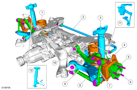
Understanding the rear suspension of your 2013 Ford Fusion is crucial for a variety of reasons. Whether you're planning to perform routine maintenance, diagnose a strange noise, or even contemplate aftermarket modifications, a solid grasp of the system's components and operation is invaluable. This guide provides a detailed breakdown of the 2013 Ford Fusion's rear suspension, catering specifically to intermediate car owners, modders, and DIY mechanics. We aim to equip you with the knowledge necessary to confidently tackle rear suspension-related tasks.
Purpose of the Diagram
A rear suspension diagram is much more than just a pretty picture. It serves as a vital resource for several key activities:
- Repair and Maintenance: Identifying worn-out parts like bushings, shocks, or springs becomes significantly easier when you can pinpoint their exact location and relationship to other components.
- Troubleshooting: A diagram assists in tracing the source of noises, vibrations, or handling issues. By visually mapping the suspension layout, you can narrow down potential problem areas.
- Modification Planning: Before attempting any modifications, such as lowering springs or upgraded shocks, a thorough understanding of the existing system is essential. The diagram helps you assess compatibility and potential challenges.
- General Knowledge: Simply learning how your car is put together fosters a deeper appreciation for its engineering and allows you to better anticipate potential problems.
Key Specs and Main Parts
The 2013 Ford Fusion utilizes a multi-link independent rear suspension. This design offers a good balance of ride comfort and handling performance. Here's a breakdown of the major components:
- Lower Control Arm (LCA): The primary load-bearing arm that connects the wheel hub to the vehicle's chassis. It's responsible for controlling wheel movement in the vertical plane.
- Upper Control Arm (UCA): Helps maintain proper wheel alignment and controls wheel camber during suspension travel.
- Toe Link: Adjusts the toe angle of the rear wheels, influencing straight-line stability and tire wear. Toe refers to the inward or outward angle of the wheels when viewed from above.
- Trailing Arm: Controls the fore-aft movement of the wheel hub, contributing to ride quality and stability during braking.
- Shock Absorber (Damper): Controls the oscillation of the suspension spring, preventing excessive bouncing and improving ride comfort and handling.
- Coil Spring: Provides the primary suspension force, supporting the vehicle's weight and absorbing road impacts.
- Wheel Hub/Bearing Assembly: Allows the wheel to rotate smoothly and provides a mounting point for the wheel.
- Stabilizer Bar (Sway Bar): Reduces body roll during cornering by connecting the left and right sides of the suspension.
- Subframe: A structural component that supports the rear suspension and isolates road noise and vibrations from the vehicle's body.
Symbols and Legend
Understanding the symbols used in the rear suspension diagram is critical for accurate interpretation. While the specific symbols might vary slightly depending on the diagram source, here are some common conventions:
- Solid Lines: Typically represent rigid components, such as control arms, subframes, and the vehicle chassis.
- Dashed Lines: Often indicate hidden components or lines of sight.
- Thick Lines: May denote primary load-bearing components.
- Thin Lines: May represent smaller components or connections.
- Arrows: Indicate direction of movement or force.
- Circles/Dots: Represent connection points or fasteners, such as bolts and nuts.
- Hatch Patterns: Can represent specific materials or indicate a cross-sectional view.
- Color Coding: While not always present, some diagrams use color to differentiate components or highlight specific systems (e.g., brake lines).
A legend or key should always accompany the diagram, providing a clear explanation of each symbol used. Carefully review the legend before attempting to interpret the diagram.
How It Works
The multi-link rear suspension works by allowing each wheel to move independently, providing better ride quality and handling compared to older, simpler designs. When a wheel encounters a bump, the suspension compresses, absorbing the impact. The lower control arm, upper control arm, and trailing arm work together to control the wheel's movement, keeping it relatively perpendicular to the road surface. The shock absorber dampens the oscillation of the coil spring, preventing excessive bouncing. The stabilizer bar reduces body roll during cornering by transferring force from one side of the suspension to the other.
The kinematics, or motion characteristics, of the multi-link system are carefully engineered to optimize handling and stability. The angles and lengths of the control arms are designed to minimize changes in wheel alignment (camber, toe, and caster) throughout the suspension's range of travel. This helps maintain consistent tire contact with the road surface, improving grip and handling.
Real-World Use: Basic Troubleshooting Tips
Here are some common issues and how the diagram can aid in diagnosis:
- Clunking Noise: Could indicate worn-out bushings in the control arms or sway bar links. Use the diagram to locate these components and visually inspect them for cracks or excessive play.
- Squeaking Noise: Often caused by dry or worn ball joints. Identify the ball joints on the control arms using the diagram and lubricate or replace them as needed.
- Uneven Tire Wear: Might be due to misaligned wheels. The diagram helps you understand the location of the toe link, which is used to adjust rear toe.
- Excessive Bouncing: Indicates worn-out shock absorbers. Locate the shocks on the diagram and inspect them for leaks or damage. A bounce test (pushing down on the rear of the vehicle and observing how quickly it settles) can also help diagnose shock absorber problems.
- Wandering or Instability: Can be caused by worn control arm bushings, or damage to suspension components after hitting potholes. The diagram will help you locate and inspect the components.
Safety Considerations
Working on the rear suspension can be dangerous if proper safety precautions are not taken. Always use jack stands to support the vehicle before working underneath it. Never rely solely on a jack. Certain components, like coil springs, store a tremendous amount of energy and can cause serious injury if released unexpectedly. Never attempt to compress or remove a coil spring without using a proper spring compressor. Also, be aware of the brake lines and ABS sensors, as they can be easily damaged during suspension work. Disconnecting brake lines will require bleeding the brakes afterward. Consult a repair manual or a qualified mechanic if you are unsure about any aspect of the repair process.
Warning: Dealing with compressed springs can be lethal. Ensure you have the right tools and knowledge. If in doubt, let a professional handle it.
By carefully studying the rear suspension diagram and following safe practices, you can confidently tackle a wide range of maintenance and repair tasks on your 2013 Ford Fusion. The diagram is a valuable tool for any DIY mechanic, providing a visual roadmap to understanding and working on this crucial part of your vehicle.
We have a detailed PDF file of the 2013 Ford Fusion Rear Suspension Diagram available for download. This file includes high-resolution images and detailed labeling for easy reference.