2013 Freightliner Cascadia Fuse Box Diagram
The 2013 Freightliner Cascadia is a workhorse, and like any complex machine, its electrical system relies heavily on a comprehensive network of fuses. Understanding the 2013 Freightliner Cascadia fuse box diagram is crucial for anyone performing electrical repairs, adding aftermarket accessories, or simply trying to diagnose a malfunctioning component. This guide will provide you with a detailed breakdown of the diagram, empowering you to confidently tackle electrical issues on your Cascadia.
Purpose of the Fuse Box Diagram
Why bother with a fuse box diagram? Several reasons: Firstly, it's invaluable for troubleshooting electrical problems. When a circuit fails, the first step is often checking the corresponding fuse. The diagram allows you to quickly locate the correct fuse without blindly pulling each one. Secondly, if you're planning to add aftermarket accessories like lights, radios, or auxiliary power outlets, knowing the fuse box layout helps you identify suitable circuits to tap into. Finally, understanding the diagram provides a deeper understanding of the truck's electrical architecture, facilitating more informed maintenance and repairs. Think of it as the roadmap to your truck's electrical nervous system.
Key Specs and Main Parts of the Fuse Box
The 2013 Freightliner Cascadia typically has multiple fuse boxes, each serving different systems. The primary fuse box is usually located inside the cabin, often on the driver's side, under the dashboard or in a side panel. There might also be a secondary fuse box under the hood, near the battery or in a separate compartment. These are often referred to as the Power Distribution Centers (PDCs).
Here's a breakdown of the main components:
- Fuses: These are sacrificial devices designed to protect circuits from overcurrent. They consist of a thin wire that melts and breaks the circuit when the current exceeds a specified amperage rating. Different fuse types (blade, cartridge) and amperage ratings are used for various circuits.
- Relays: Electrically operated switches used to control high-current circuits with low-current signals. For example, the starter motor relay allows the ignition switch to activate the starter without carrying the full starter motor current.
- Circuit Breakers: Similar to fuses, but resettable. They trip and interrupt the circuit in case of overcurrent, but can be reset once the fault is cleared. Circuit breakers are typically used for circuits that may experience temporary overloads.
- Fuse Box Housing: The physical enclosure that houses the fuses, relays, and circuit breakers. It's usually made of plastic and provides protection from the environment.
- Terminal Blocks/Bus Bars: These are conductive strips that provide a common connection point for multiple circuits. They facilitate organized wiring and ensure reliable connections.
- Wiring Harnesses: Bundles of wires that connect the fuse box to various components throughout the truck. They're typically color-coded for easy identification.
Understanding Fuse Box Symbols, Lines and Colors
The fuse box diagram uses symbols, lines, and colors to convey information about each circuit. Learning to interpret these elements is key to using the diagram effectively.
- Lines: Lines represent wires connecting components. The thickness of the line may indicate the wire gauge (thicker lines for higher current circuits).
- Colors: Wires are often color-coded according to their function. Common colors include red (power), black (ground), and various other colors for signal wires. The diagram should include a color code legend. However, never solely rely on the color of a wire for identification; always use a multimeter to verify the voltage and circuit.
- Symbols:
- Fuse Symbol: A zigzag line inside a rectangle. The number next to the symbol indicates the fuse's amperage rating (e.g., 10A, 20A).
- Relay Symbol: A rectangle with a coil and a switch. The coil represents the relay's electromagnet, and the switch represents the contacts that open or close the circuit.
- Circuit Breaker Symbol: Similar to a fuse symbol, but with a curved line above the zigzag.
- Ground Symbol: Usually three horizontal lines decreasing in length, connected to the chassis.
- Component Symbols: The diagram will include symbols for various components, such as headlights, tail lights, horn, etc.
A key part of understanding the diagram is recognizing how it's organized. Typically, circuits are grouped by function (e.g., lighting, engine control, cab accessories). The diagram will often include a table that lists each fuse, its amperage rating, and the components it protects.
How the Fuse Box Works: A Simplified Explanation
Imagine the fuse box as a central distribution point for electrical power. Power from the battery flows into the fuse box, and from there, it's distributed to various circuits throughout the truck. Each circuit has a fuse that's sized to protect the wiring and components from overcurrent. When a short circuit or overload occurs, the fuse blows, interrupting the flow of electricity and preventing damage to the circuit.
Relays allow low-current circuits to control high-current circuits. For example, when you turn on the headlights, a small amount of current flows through the headlight switch to the headlight relay. The relay then closes, allowing a much larger current to flow from the battery to the headlights. This prevents the headlight switch from being overloaded and burning out.
Therefore, always respect the amperage ratings on the fuse box. Never replace a fuse with a higher-rated fuse, as this can lead to overheating and potentially a fire. If a fuse repeatedly blows, there is likely a short circuit or overload in the circuit that needs to be diagnosed and repaired.
Real-World Use: Basic Troubleshooting Tips
Here's how to use the fuse box diagram to troubleshoot common electrical problems:
- Identify the Problem: Determine which component is not working (e.g., headlights, horn, wipers).
- Consult the Diagram: Locate the fuse or relay that corresponds to the malfunctioning component.
- Inspect the Fuse: Remove the fuse and visually inspect it. A blown fuse will have a broken filament. You can also use a multimeter to check for continuity across the fuse.
- Replace the Fuse: If the fuse is blown, replace it with a fuse of the same amperage rating.
- Test the Circuit: After replacing the fuse, test the component to see if it's working.
- Investigate Further: If the fuse blows again immediately, there's a short circuit or overload in the circuit. You'll need to trace the wiring and components to find the source of the problem. This may involve using a multimeter to check for voltage drops and continuity.
Safety Considerations
Working with electrical systems can be dangerous. Always take the following precautions:
- Disconnect the Battery: Before working on any electrical circuit, disconnect the negative terminal of the battery to prevent accidental shocks or short circuits.
- Use Proper Tools: Use insulated tools and wear safety glasses.
- Avoid Water: Never work on electrical systems in wet conditions.
- Identify High-Risk Components: Be aware of components that carry high voltage or current, such as the starter motor, alternator, and ignition system. These components can pose a serious shock hazard. Consider having a qualified mechanic work on these components.
Remember: High voltage components like the ignition system and charging system can store energy even after the battery is disconnected. Exercise extreme caution when working near these components. Discharging capacitors or waiting for a safe discharge time is crucial before touching them.
By understanding the fuse box diagram and following these safety precautions, you can confidently diagnose and repair electrical problems on your 2013 Freightliner Cascadia. This knowledge will save you time and money, and empower you to keep your truck running smoothly.
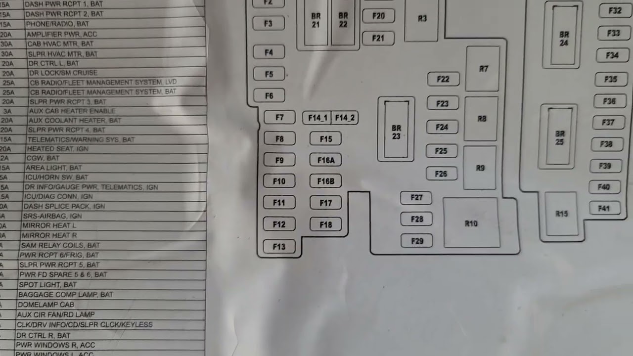
We have a detailed 2013 Freightliner Cascadia Fuse Box Diagram available for download. This document will provide you with a visual representation of the fuse box layout, including fuse locations, amperage ratings, and circuit descriptions. With this diagram in hand, you'll be well-equipped to tackle any electrical challenge that comes your way. Contact us for access.