2013 Gmc Sierra Radio Wiring Diagram
Alright, let's dive into the radio wiring diagram for the 2013 GMC Sierra. Whether you're planning to upgrade your sound system, troubleshoot a pesky electrical issue, or just better understand how your truck's audio system works, having a good grasp of this diagram is crucial. This isn't just a random collection of wires; it's a roadmap to your audio experience!
Purpose of the 2013 GMC Sierra Radio Wiring Diagram
Think of this diagram as your truck's audio system's DNA. It's essential for:
- Repairs: Pinpointing and fixing broken wires, short circuits, or faulty components.
- Upgrades: Safely installing aftermarket stereos, amplifiers, speakers, or other audio enhancements.
- Troubleshooting: Diagnosing issues like no sound, distorted audio, or battery drain related to the radio.
- Learning: Gaining a deeper understanding of your vehicle's electrical system and how the radio integrates with it.
- Customization: Modifying your audio system with confidence, knowing where each wire leads.
Key Specs and Main Parts
Before we dive into the diagram itself, let's cover some essential components you'll encounter:
- Head Unit: The heart of the system – the radio itself. It's responsible for receiving signals, processing audio, and controlling other components.
- Speakers: These convert electrical signals into audible sound. The 2013 Sierra typically has speakers in the front doors, rear doors (depending on the cab configuration), and sometimes tweeters in the A-pillars.
- Amplifier (if equipped): Some Sierras come with a factory amplifier to boost the audio signal to the speakers. If your truck has a Bose system, it *definitely* has an amplifier. The location of the factory amp varies, but it's often under the center console or behind a rear seat.
- Wiring Harness: A bundle of wires that connects the radio to the vehicle's electrical system, speakers, and other components.
- Ground Connection: Crucial for completing the electrical circuit. Poor grounding is a common cause of audio problems.
- Power Wire (B+): Supplies constant 12V power to the radio for memory functions (clock, presets, etc.).
- Accessory Wire (ACC): Provides power to the radio when the ignition is turned on.
- Speaker Wires: Carry the audio signal from the radio or amplifier to the speakers.
- Data Bus (CAN bus): This is how the radio communicates with other vehicle systems (like the OnStar module or steering wheel controls).
Understanding the Wiring Diagram: Symbols, Lines, and Colors
A wiring diagram is a symbolic representation of the electrical circuit. Learning to interpret these symbols is key. Here’s a breakdown:
- Lines: Represent wires. Thicker lines might indicate higher current-carrying capacity.
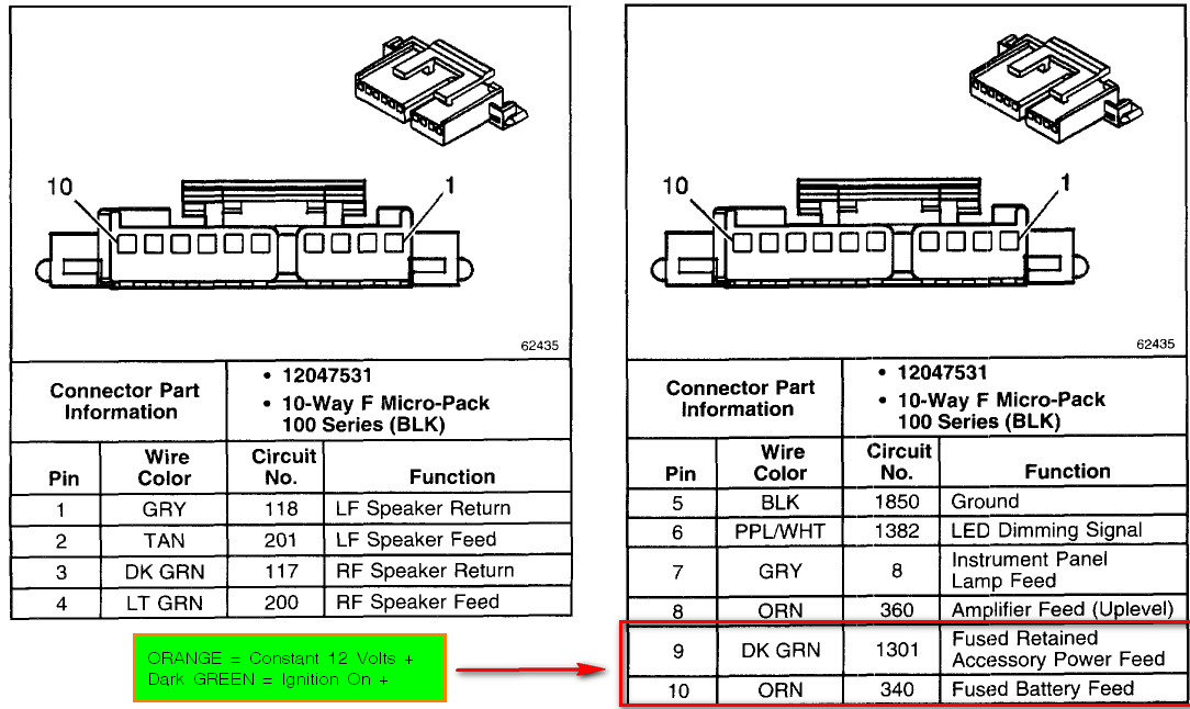
- Colors: Each wire is assigned a specific color code. This is crucial for identifying wires in the harness. Common colors include red (power), black (ground), yellow (accessory), and various colors for speaker wires. The diagram will include a color key explaining each color code. Pay *close* attention to the color abbreviations, as they might use two-letter codes (e.g., LT BLU for Light Blue).
- Symbols:
- Circles: Can represent connectors or terminals.
- Squares: Can represent components like relays or switches.
- Resistors: Represented by a jagged line.
- Capacitors: Represented by two parallel lines.
- Ground: A symbol that looks like a downward-pointing arrow or a series of horizontal lines decreasing in size.
- Fuses: Represented by a squiggly line inside a rectangle or a simple rectangle.
- Abbreviations: The diagram uses abbreviations for components and wire colors (e.g., AMP for Amplifier, GND for Ground).
Remember to consult the legend or key that accompanies the wiring diagram. This legend will provide a detailed explanation of all the symbols, abbreviations, and color codes used.
How It Works: Tracing the Circuit
Let's walk through a simplified example of how the radio circuit works:
- Power Supply: The battery provides power to the system. The power wire (B+) runs from the battery, through a fuse (for protection), to the radio.
- Ignition Signal: The accessory wire (ACC) receives power when the ignition is turned on. This signal tells the radio to turn on.
- Grounding: The ground wire connects the radio to the vehicle's chassis, providing a return path for the electrical current.
- Audio Signal Processing: The radio receives audio signals from various sources (AM/FM tuner, CD player, auxiliary input, Bluetooth). It processes these signals and sends them to the amplifier (if equipped).
- Amplification: The amplifier boosts the audio signal.
- Speaker Output: The amplified signal is sent to the speakers via the speaker wires. Each speaker has a positive (+) and negative (-) wire.
By following the wires on the diagram, you can trace the flow of electricity and audio signals through the system. This allows you to identify potential points of failure.
Real-World Use: Basic Troubleshooting Tips
Here are some common problems and how the wiring diagram can help you troubleshoot them:
- No Power to Radio:
- Check the fuses related to the radio (usually labeled "Radio" or "Audio" in the fuse box). Use the diagram to locate the correct fuse.
- Verify that the power wire (B+) and accessory wire (ACC) are receiving voltage with a multimeter.
- Check the ground connection. Ensure it's clean and securely attached to the chassis. A loose or corroded ground is a frequent culprit.
- No Sound from Speakers:
- Check the speaker wires for damage or disconnection.
- If you have an amplifier, verify that it's receiving power and is properly grounded.
- Test the speakers themselves to rule out a blown speaker.
- Use a multimeter to check for continuity in the speaker wires.
- Distorted Sound:
- Check the speaker wires for shorts or damage.
- Inspect the speakers for damage.
- If you have an amplifier, it could be faulty.
- Battery Drain:
- This is a tricky one, but the diagram can help you isolate the radio as the source of the drain. Disconnect the radio and monitor the battery voltage. If the drain disappears, the radio is likely the problem. A faulty amplifier or a short circuit in the wiring can cause battery drain.
Safety First! Working with Electrical Components
Working with automotive electrical systems can be dangerous. Here are some safety precautions:
- Disconnect the Battery: Always disconnect the negative battery cable before working on any electrical components. This prevents accidental shorts and potential electrical shocks.
- Use a Multimeter: A multimeter is essential for testing voltage, continuity, and resistance. Learn how to use it safely and accurately.
- Be Careful with Airbags: Airbags are sensitive to electrical changes. Avoid tampering with any wiring near airbag modules. Consult a professional if you're unsure.
- Work in a Well-Lit Area: Good lighting is essential for seeing what you're doing and avoiding mistakes.
- Don't Work When Tired or Distracted: Electrical work requires focus and concentration.
- High Current Components: Be particularly cautious when dealing with the main power wire (B+) and the amplifier (if equipped). These components can carry significant current and pose a greater risk of electrical shock.
Remember, if you are not comfortable working with electrical systems, it's best to consult a qualified automotive electrician.
We have the complete 2013 GMC Sierra radio wiring diagram file available for download. This detailed diagram will be an invaluable resource for your repairs, upgrades, and troubleshooting. Good luck, and stay safe!