2013 Hyundai Elantra Tail Light Wiring Harness
So, you're diving into the tail light wiring harness of your 2013 Hyundai Elantra? Excellent choice! Understanding this often-overlooked system can save you a bundle on repairs, help with custom modifications, and give you a deeper understanding of your vehicle's electrical system. This guide will walk you through the intricacies of the wiring diagram, focusing on practical applications and troubleshooting tips. We'll break down the jargon and explain the key components, making it approachable even if you're not an electrical engineer.
Purpose of Understanding the Tail Light Wiring Diagram
Why bother with a tail light wiring diagram? Several reasons: First, it's indispensable for repairs. A blown fuse is one thing, but a short circuit or damaged wire requires a more targeted approach. The diagram helps you pinpoint the problem area quickly and accurately. Second, it's vital for custom modifications. Thinking of adding aftermarket lights, a trailer hitch with lighting, or even just upgrading to brighter bulbs? The diagram allows you to safely tap into the existing system without causing damage or triggering error codes. Third, and perhaps most importantly, it enhances your overall understanding of automotive electrical systems. Knowing how the tail lights are wired provides a foundation for tackling other electrical projects on your Elantra or any other vehicle. This knowledge empowers you to diagnose and fix problems yourself, saving time and money.
Key Specs and Main Parts of the 2013 Elantra Tail Light Wiring Harness
The 2013 Elantra's tail light system, like most modern vehicles, is a complex network of wires, connectors, and modules. Here's a breakdown of the main parts:
- Tail Light Assembly: This is the housing that contains all the bulbs and reflectors. It usually includes the brake light, tail light, turn signal, and reverse light.
- Bulbs: These are the light sources. The 2013 Elantra likely uses a combination of incandescent and possibly some early LED-style bulbs, depending on the trim level. Each bulb has a specific wattage and voltage requirement.
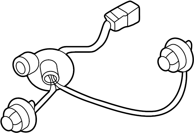
- Wiring Harness: This is the bundle of wires that connects the tail light assembly to the vehicle's electrical system. The harness contains individual wires for each light function (brake, tail, turn, reverse).
- Connectors: These are the plastic plugs that connect the wiring harness to the tail light assembly and the vehicle's main wiring system. They provide a secure and weatherproof connection.
- Fuses: These are safety devices that protect the electrical circuits from overloads. A blown fuse is often the first sign of a problem in the tail light system. The fuse box location and fuse number dedicated to tail lights will be specified in your owner's manual or on a diagram located inside the fuse box cover.
- Ground Connection: This is a crucial connection that provides a return path for the electrical current. A poor ground connection can cause all sorts of weird electrical problems. Typically found as a wire bolted to the chassis.
- Body Control Module (BCM): This electronic module controls various body functions, including the tail lights. It receives signals from the brake switch, turn signal switch, and other sensors, and then activates the appropriate lights. Some advanced features, such as bulb failure detection, are managed by the BCM.
Key Specs: While specific wire gauges are less crucial to memorise initially, knowing the voltage is critical. The Elantra's tail light system operates on 12V DC (Direct Current). Therefore, all your testing and replacement components must be rated for 12V DC.
Understanding the Wiring Diagram Symbols
A wiring diagram is essentially a roadmap of the electrical system. It uses symbols to represent the various components and their connections. Here's a breakdown of some common symbols you'll encounter in the 2013 Elantra's tail light wiring diagram:
- Solid Lines: Represent wires. The thickness of the line does *not* necessarily indicate wire gauge.
- Dashed Lines: Often represent shielded cables, ground connections, or connections to other systems.
- Circles: Represent bulbs or lamps.
- Rectangles: Represent connectors, switches, relays, or modules (like the BCM). Labels inside the rectangle identify the component.
- Ground Symbol: Typically looks like three horizontal lines stacked on top of each other, getting progressively shorter. Indicates a connection to the vehicle's chassis (ground).
- Color Codes: Wires are often color-coded to help identify them. Common colors include Black (ground), Red (power), and various other colors for specific functions. The diagram will usually include a key that explains the color codes. Common abbreviations include: BK (Black), RD (Red), WH (White), GN (Green), BL (Blue), YL (Yellow), OR (Orange).
- Numbers/Letters: These often represent connector pin numbers or wire circuit numbers. These are critical for accurate troubleshooting and ensuring you are testing the correct wire.
Example: A solid red line connecting the battery (represented by a symbol) to a fuse (represented by a rectangle) indicates a power wire running from the battery to the fuse. A black wire running from a tail light bulb to the chassis ground indicates the ground connection for that bulb.
How the 2013 Elantra Tail Light System Works
The tail light system operates based on a series of switches and signals. When you turn on the headlights, the tail lights activate. Pressing the brake pedal activates the brake lights. Activating the turn signal lever activates the turn signal lights on the corresponding side of the vehicle. Putting the car in reverse activates the reverse lights.
The sequence typically looks like this:
- A switch is activated (e.g., brake pedal switch, turn signal switch).
- The switch sends a signal to the BCM or directly to the appropriate circuit.
- The BCM (if involved) processes the signal and sends power to the corresponding light.
- The light illuminates, completing the circuit to ground.
The BCM plays a central role in controlling many of these functions, especially advanced features like bulb failure detection. If a bulb burns out, the BCM may detect the change in current flow and trigger a warning light on the dashboard.
Real-World Use: Basic Troubleshooting Tips
Here are some common tail light problems and how to troubleshoot them using the wiring diagram:
- No Tail Lights: Check the fuse first! Use a multimeter to test the fuse for continuity. If the fuse is blown, replace it with the same amperage rating. If the fuse blows again immediately, there's likely a short circuit in the wiring. Use the diagram to trace the wiring and look for damaged insulation or pinched wires.
- One Tail Light Not Working: Check the bulb first. Replace it with a new bulb of the correct type. If the new bulb doesn't work, check the connector for corrosion or damage. Use the wiring diagram to test the voltage at the connector. If there's no voltage, trace the wiring back to the fuse box or BCM.
- Turn Signal Not Working: Check the bulb and the flasher relay. The wiring diagram will show the location of the flasher relay. If the flasher relay is working, check the turn signal switch and the wiring to the tail light assembly.
- Brake Lights Not Working: Check the brake light switch, which is typically located near the brake pedal. The wiring diagram will show the location of the switch and the wiring to the brake lights.
Using a Multimeter: A multimeter is essential for troubleshooting electrical problems. Use it to test for voltage, continuity, and resistance. Make sure you know how to use the multimeter safely and accurately before working on the electrical system. When testing, always reference the wiring diagram to identify the correct wires to test. Note that some circuits are only live when the ignition is on.
Safety Considerations
Working on automotive electrical systems can be dangerous. Always disconnect the negative battery terminal before working on any electrical components. This prevents accidental shorts and shocks. Be especially careful when working near the airbag system. Accidental activation of the airbags can cause serious injury. Refer to your service manual for proper airbag disabling procedures if necessary. Never probe wires with sharp objects, as this can damage the insulation and create a short circuit. Always use properly insulated tools. Remember, electricity can be lethal; always prioritize safety.
High-Risk Components: The BCM and any wiring related to airbags or anti-lock brakes should be approached with extreme caution. If you are not comfortable working on these systems, it's best to consult a qualified technician.
We have a detailed 2013 Hyundai Elantra Tail Light Wiring Diagram file available for download. This diagram will provide you with a visual reference for all the components and wiring connections discussed in this article. Having access to the diagram will greatly assist you in troubleshooting and repairing your vehicle's tail light system. Good luck, and remember to work safely!