2013 Hyundai Sonata Fuse Box Diagram
The 2013 Hyundai Sonata, a popular mid-size sedan, relies on a complex electrical system. Navigating this system becomes significantly easier with a solid understanding of its fuse box diagram. This guide provides an in-depth look at the fuse box diagram for the 2013 Sonata, equipping you with the knowledge to diagnose electrical issues, perform basic repairs, and even undertake some modifications.
Purpose of the Fuse Box Diagram
The fuse box diagram is essentially a roadmap of your car's electrical circuits. It shows the location of each fuse and relay, along with the components they protect. This diagram is invaluable for:
- Troubleshooting Electrical Problems: Identifying a blown fuse is the first step in fixing many electrical issues. The diagram tells you which fuse corresponds to which circuit (e.g., headlights, radio, power windows).
- Performing Repairs: Knowing the fuse location helps you quickly isolate and address faulty components.
- Adding Accessories: When installing aftermarket accessories (e.g., a new stereo system, auxiliary lights), the diagram helps you tap into appropriate power sources safely and avoid overloading circuits.
- Understanding Your Vehicle: Familiarizing yourself with the electrical system's architecture gives you a deeper understanding of your car's operation.
Key Specs and Main Parts
The 2013 Sonata typically has two fuse boxes: one located inside the cabin (usually under the dashboard on the driver's side) and another in the engine compartment (near the battery). Each fuse box contains fuses, relays, and sometimes circuit breakers. Here’s a breakdown:
- Fuses: These are the most common component. They are safety devices designed to protect electrical circuits from overcurrent. Each fuse has a specific amperage rating (e.g., 10A, 15A, 20A), indicating the maximum current it can handle before blowing.
- Relays: Relays are electromechanical switches. They use a small electrical current to control a larger current, allowing low-current circuits to switch on high-current devices (e.g., headlights, starter motor).
- Circuit Breakers: These are similar to fuses but can be reset after tripping. They are less common in modern vehicles, but some circuits may still use them.
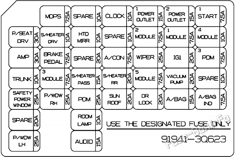
The diagram itself presents this information in a structured format. It’s usually a schematic representation of the fuse box, with each fuse and relay labeled. Crucially, the diagram will list what each fuse/relay protects (e.g., "HEAD LH" for the left headlight).
Understanding the Symbols, Lines, and Colors
Fuse box diagrams use symbols and conventions to convey information efficiently. Understanding these symbols is key to interpreting the diagram correctly.
- Fuse Symbols: Fuses are typically represented by a zig-zag line enclosed in a rectangle or a simple rectangle.
- Relay Symbols: Relays are shown as a coil (representing the electromagnet) and a switch (representing the contacts). The coil is typically drawn as a series of loops.
- Lines: Lines connect fuses and relays to the components they protect. Thicker lines may indicate higher current circuits.
- Colors: While the diagram itself might not be in color, the actual wires leading to the fuses are color-coded. Knowing standard automotive wiring color codes (e.g., red for power, black for ground) can be helpful when tracing circuits. However, always refer to the specific wiring diagram for your model year as color coding can vary.
- Icons/Abbreviations: The diagram utilizes abbreviations to denote the protected components (e.g., "ECM" for Engine Control Module, "ABS" for Anti-lock Braking System, "IG" for Ignition). A legend accompanying the diagram should explain these abbreviations.
Important Technical Term: Amperage is the measure of electrical current. A higher amperage fuse protects circuits that draw more power.
How It Works
The fuse box acts as a central distribution point for electrical power. Power from the battery flows through the fuse box and is distributed to various circuits throughout the vehicle. Each circuit is protected by a fuse of the appropriate amperage rating.
When a fault occurs in a circuit (e.g., a short circuit), the current flowing through that circuit increases dramatically. This excessive current heats up the fuse element, causing it to melt and break the circuit. This prevents damage to the wiring and components connected to that circuit.
Relays work by using a small current to activate an electromagnet. When the electromagnet is energized, it pulls a switch, completing a separate, high-current circuit. This allows components like headlights, which require a lot of power, to be controlled by a smaller switch on the dashboard.
Real-World Use and Basic Troubleshooting
Here's how you can use the fuse box diagram for basic troubleshooting:
- Identify the Problem: Determine which component is not working (e.g., the windshield wipers, the cigarette lighter).
- Consult the Diagram: Locate the fuse or relay that controls the malfunctioning component in the fuse box diagram.
- Inspect the Fuse: Visually inspect the fuse. A blown fuse will have a broken filament. You can also use a multimeter to check for continuity across the fuse. A reading of zero indicates a blown fuse.
- Replace the Fuse: Replace the blown fuse with a new fuse of the same amperage rating. Never use a fuse with a higher amperage rating, as this could damage the circuit.
- Test the Component: After replacing the fuse, test the component to see if it is working again.
If the fuse blows again immediately after replacement, there is likely a more serious problem in the circuit, such as a short circuit. In this case, further diagnosis is required, and you may need to consult a professional mechanic.
Important Technical Term: Continuity refers to an uninterrupted electrical path. A multimeter in continuity mode will beep if there is a complete circuit.
Safety Precautions
Working with electrical systems can be dangerous. Always follow these safety precautions:
- Disconnect the Battery: Before working on any electrical components, disconnect the negative terminal of the battery to prevent accidental shocks.
- Use Proper Tools: Use insulated tools to avoid short circuits.
- Never Bypass Fuses: Never bypass a fuse with a wire or a piece of metal. This eliminates the safety protection and could cause a fire.
- Identify High-Risk Components: Components like the airbag system are extremely sensitive and should only be handled by qualified technicians. Refer to your vehicle's service manual for specific safety instructions related to the airbag system.
Crucially, the components related to the airbag system are often easily identified in the fuse box diagram. These components have specific and are crucial for the safety of the vehicle's occupants. Do not attempt to modify or repair these circuits without proper training and certification.
Disclaimer: This guide provides general information only. Always consult the specific fuse box diagram for your 2013 Hyundai Sonata model and refer to the vehicle's service manual for detailed instructions and safety precautions.
We have a detailed 2013 Hyundai Sonata Fuse Box Diagram available for download. This document provides a comprehensive visual guide, including fuse locations, amperage ratings, and associated circuits. It's an invaluable resource for any DIYer or experienced mechanic working on this vehicle.