2013 Hyundai Sonata Tail Light Wiring Harness
Let's dive into the world of the 2013 Hyundai Sonata's tail light wiring harness. This article aims to provide you, the experienced DIYer or car enthusiast, with a comprehensive understanding of this critical system. Whether you're tackling a repair, customizing your Sonata, or simply seeking a deeper understanding of its inner workings, a solid grasp of the tail light wiring is essential. We'll break down the diagram, explain its components, and offer practical troubleshooting tips to empower you to tackle any tail light related challenge.
Purpose and Importance
The tail light wiring harness is the nervous system of your Sonata's rear lighting. It's the interconnected network of wires that delivers electrical power to your tail lights, brake lights, turn signals, and potentially reverse lights. Understanding the diagram is crucial for several reasons:
- Repairs: Quickly identify and fix shorts, breaks, or corrosion within the wiring system.
- Modifications: Safely install aftermarket tail lights, LED upgrades, or other custom lighting solutions.
- Troubleshooting: Diagnose lighting problems systematically, saving time and money compared to guesswork.
- General Understanding: Gain a deeper knowledge of your vehicle's electrical system.
Key Specs and Main Parts of the Tail Light Wiring Harness
The 2013 Hyundai Sonata utilizes a 12V DC (Direct Current) electrical system. The tail light wiring harness is generally composed of the following key components:
- Wiring: Stranded copper wires of varying gauges (thicknesses) carry electrical current. The gauge, often indicated as AWG (American Wire Gauge), dictates the current-carrying capacity. Thicker wires (lower AWG numbers) handle higher currents.
- Connectors: These are plastic housings with metal terminals that facilitate the connection between different wires and the light bulbs or LED modules. Connectors may be weatherproofed with rubber seals to prevent corrosion. Common connector types include inline connectors, pigtail connectors, and multi-pin connectors.
- Ground Points: These are crucial connection points where the wiring harness is electrically connected to the vehicle's chassis. A good ground connection provides a return path for the electrical current, completing the circuit. Corrosion at ground points is a common cause of lighting problems.
- Sockets: These components physically hold the light bulbs or LED modules and provide the electrical connection to them. They are designed for specific bulb types (e.g., 7443 for brake/tail lights).
- Fuses: These safety devices are designed to protect the electrical circuits from overcurrent. A blown fuse indicates a problem in the circuit. Fuses are rated in amperes (amps), which indicates the maximum current they can safely handle.
- Relays: Relays are electromechanical switches that control high-current circuits using a low-current signal. They are often used in lighting systems to protect the vehicle's switches from excessive wear.
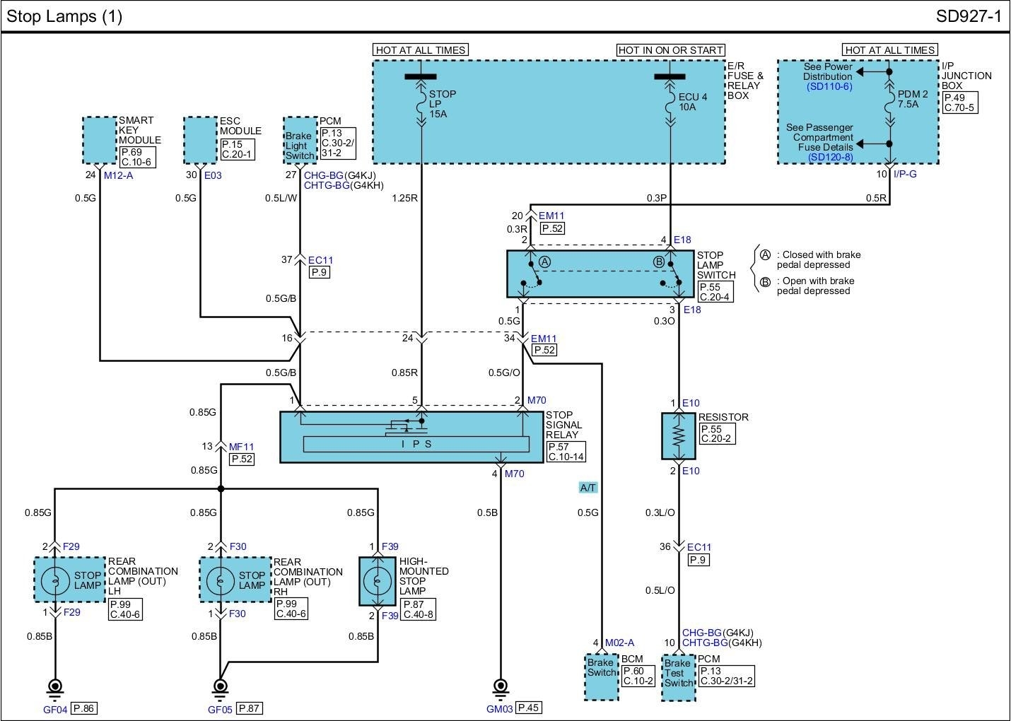
Decoding the Tail Light Wiring Diagram: Symbols and Conventions
Understanding the wiring diagram's symbols and conventions is paramount. Here's a breakdown:
- Lines: Solid lines represent wires. Dashed lines may indicate shielding or grounds.
- Colors: Each wire is typically identified by a color code (e.g., BLK - Black, RED - Red, GRN - Green, YEL - Yellow, BLU - Blue, WHT - White). These color codes are essential for tracing wires and identifying circuits. Color codes can vary slightly depending on the specific sub-model of the 2013 Sonata.
- Symbols for Components: These can vary slightly, but common symbols include:
 Resistor (used rarely in tail light circuits)
 Capacitor (also rare in tail light circuits)
 Diode (common in LED circuits)
 Light Bulb
- Ground Symbol:

- Battery Symbol.
- Switch Symbol.
- Numbers and Letters: These indicate wire gauges, connector pin numbers, and component designations.
- Abbreviations: Learn common abbreviations like GND (Ground), SIG (Signal), PWR (Power), and B+ (Battery Positive).
How the Tail Light Wiring System Works
The tail light wiring system is a relatively straightforward circuit. When you turn on your headlights, a switch activates the tail light circuit, sending power from the battery through the wiring harness to the tail light bulbs. Similarly, when you press the brake pedal, another switch activates the brake light circuit, sending power to the brake light bulbs. The turn signal circuit is activated by the turn signal stalk, which controls a flasher relay that intermittently sends power to the appropriate turn signal bulbs.
A critical aspect is the grounding. Each light needs a good ground connection to complete the circuit. Without a proper ground, the light will not illuminate, or may illuminate dimly or erratically.
Real-World Use: Basic Troubleshooting Tips
Here are some common tail light wiring issues and how to troubleshoot them:
- A Light Doesn't Work:
- Check the bulb first. Replace it with a known good bulb.
- Check the fuse associated with that light. Replace if blown.
- Inspect the socket for corrosion or damage. Clean or replace if necessary.
- Use a multimeter to check for voltage at the socket. If no voltage is present, trace the wiring back to the fuse box, checking for breaks or loose connections.
- Verify the ground connection is secure and free of corrosion.
- All Tail Lights Don't Work:
- Check the main tail light fuse.
- Inspect the headlight switch.
- Check the ground connection for the entire tail light harness.
- Turn Signal Blinks Too Fast (Hyperflashing): This usually indicates a burned-out bulb on that side of the car or an LED bulb without proper resistance (if you've upgraded to LEDs).
- Intermittent Lighting Problems: These are often caused by loose connections or corroded terminals. Carefully inspect all connectors and grounds, cleaning and tightening them as needed. A dielectric grease can help prevent future corrosion.
Safety Considerations
Working with automotive electrical systems can be dangerous. Always observe the following safety precautions:
- Disconnect the Battery: Disconnect the negative (-) terminal of the battery before working on any electrical component to prevent accidental shorts and electrical shocks.
- Use Proper Tools: Use insulated tools designed for automotive electrical work.
- Work in a Well-Ventilated Area: Some electrical components can emit fumes when overheated.
- Identify Circuits Carefully: Refer to the wiring diagram to ensure you are working on the correct circuit.
- Avoid Working on Live Circuits: If you must work on a live circuit, use extreme caution and wear appropriate personal protective equipment (PPE).
- Airbags: Be especially careful when working near airbag components. Accidental activation can cause serious injury.
The ABS (Anti-lock Braking System) and other safety-related systems are integrated with the vehicle's electrical system. Incorrect wiring or repairs can compromise their functionality. If you're unsure about any aspect of the repair, consult a qualified mechanic.
Remember to double-check your work and test the system thoroughly after making any repairs. A little patience and attention to detail can save you time, money, and frustration in the long run.
For your convenience, we have a detailed wiring diagram file specifically for the 2013 Hyundai Sonata's tail light system. You can download it here.