2013 Kia Sportage 2.0 Starter Location Diagram Silverado
Alright, let's dive into the starter system for the 2013 Kia Sportage 2.0L engine. This article focuses on understanding the starter location diagram, which is absolutely crucial whether you're tackling a starter replacement, diagnosing electrical issues, or simply want to deepen your understanding of your vehicle's inner workings. Having this information at your fingertips can save you time, money, and a whole lot of frustration.
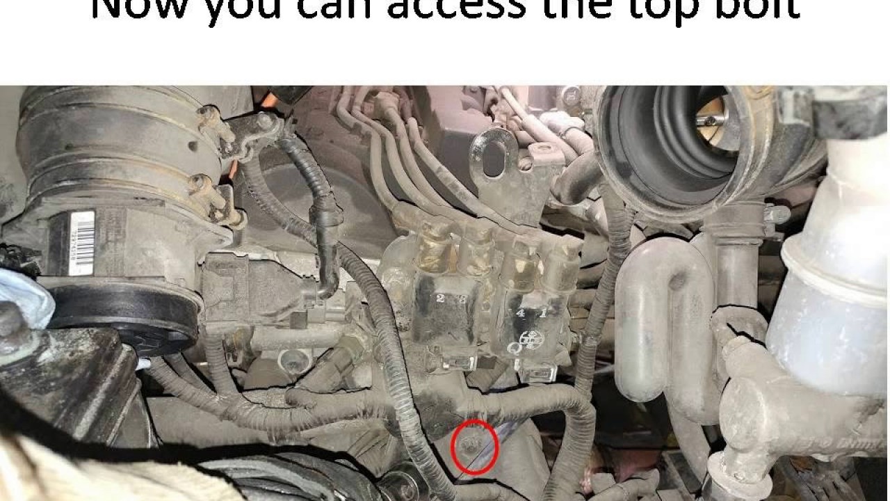
Why This Diagram Matters
Think of the starter system diagram as a roadmap to your engine's starting process. Without it, you're essentially navigating a complex electrical circuit blindfolded. The diagram helps you:
- Locate components quickly and accurately: No more fumbling around in the dark trying to find the starter.
- Trace wiring issues: See the electrical pathways and identify potential shorts, open circuits, or corroded connections.
- Understand the circuit: Learn how the various components interact to crank the engine.
- Plan repairs and modifications: Knowing the system layout allows you to prepare for repairs and even consider safe and informed modifications.
Key Specs and Main Parts of the 2013 Kia Sportage 2.0L Starter System
Before we get into the diagram specifics, let's define the key players. We're talking about a 2.0L inline four-cylinder engine in the 2013 Kia Sportage, so some specifics may vary slightly based on trim, but the core components remain consistent:
- Starter Motor: The heart of the system, responsible for physically cranking the engine to initiate combustion. These typically have a 12V DC motor.
- Solenoid: An electromagnetic switch attached to the starter. It receives the signal from the ignition switch and engages the starter motor with the flywheel. Think of it as the 'go' button for the starter.
- Flywheel/Flexplate: A large, toothed wheel attached to the engine crankshaft. The starter's pinion gear engages with these teeth to turn the engine. (Note: Flywheel for manual transmissions, flexplate for automatics.)
- Battery: Provides the electrical power needed to operate the starter motor. Typically a 12V battery, and its condition is paramount.
- Ignition Switch: The switch you turn with your key. It sends the initial signal to the solenoid.
- Wiring and Cables: Connect all the components. These are crucial; a bad connection or damaged cable can prevent the starter from working. Heavy gauge wires are used due to the high current demand.
- Fuses and Relays: Protect the circuit from overloads and control the flow of electricity.
Understanding the Diagram's Symbols
Starter system diagrams use a standardized set of symbols to represent the different components and connections. Deciphering these symbols is key to understanding the diagram.
- Solid Lines: Represent wires carrying electrical current. Thicker lines often indicate wires carrying higher current (e.g., the cable from the battery to the starter).
- Dashed Lines: May represent ground connections or control wires with lower current.
- Circles: Typically represent components such as relays, solenoids, or fuses.
- Rectangles: Can represent switches, sensors, or other electronic modules.
- Ground Symbol (Often looks like an upside-down Christmas tree): Indicates a connection to the vehicle's chassis, providing a return path for the current.
- Resistor Symbol (Zig-zag line): Represents a component that resists the flow of current.
- Capacitor Symbol (Two parallel lines): Represents a component that stores electrical energy.
Colors in the diagram are also important. Common conventions include:
- Red: Often represents a positive (12V) power supply.
- Black: Typically represents ground.
- Other Colors (Blue, Green, Yellow, etc.): Represent different control or signal wires.
Remember to always refer to the specific legend provided with the diagram you're using. Color coding can vary slightly between manufacturers.
How It Works: A Simplified Explanation
The starter system's operation is relatively straightforward. Here's a breakdown:
- Turning the Key: When you turn the ignition key to the "Start" position, it sends a signal to the starter relay (sometimes directly to the solenoid, but often through a relay for safety and current management).
- Relay Activation (If Applicable): The starter relay, if present, closes, sending a signal to the starter solenoid.
- Solenoid Engagement: The solenoid uses electromagnetism to perform two key functions:
- It pushes the starter's pinion gear into engagement with the flywheel/flexplate teeth.
- It closes a high-current electrical contact, allowing the battery's full power to flow to the starter motor.
- Engine Cranking: The starter motor spins rapidly, turning the engine's crankshaft. This draws in air and fuel, and the engine begins to run.
- Disengagement: Once the engine starts, you release the key, the solenoid retracts the pinion gear, and the starter motor stops.
Real-World Use: Basic Troubleshooting Tips
Here are a few troubleshooting tips using the starter location diagram:
- "Clicking" Sound: If you hear a single click but the engine doesn't crank, it could indicate a weak battery, a corroded connection at the solenoid, or a faulty solenoid itself. Use the diagram to check the wiring and connections to the solenoid. Clean any corrosion and test the battery voltage.
- No Sound at All: Check the fuse for the starter circuit using the diagram to locate it. Also, verify the ignition switch is functioning correctly. A faulty ignition switch won't send the signal to the solenoid.
- Slow Cranking: Could be a sign of a weak battery, corroded battery terminals, or a failing starter motor. Use a multimeter to test the voltage drop across the battery terminals while cranking the engine. A significant voltage drop (below 9.6V) indicates a battery problem.
- Starter Stays Engaged: A rare but potentially dangerous issue. This could be a faulty solenoid that's not retracting properly. Disconnecting the battery is the first step to prevent damage to the starter and flywheel.
Always use a multimeter to test for voltage and continuity. This is the most reliable way to diagnose electrical issues.
Safety First: Handling Risky Components
The starter system involves high currents and potentially dangerous components. Exercise extreme caution:
- Disconnect the Battery: Always disconnect the negative battery cable before working on the starter system. This prevents accidental shorts and electrical shocks.
- High Current: The starter motor draws a significant amount of current. Avoid touching any exposed wires while the system is active.
- Hot Components: The starter motor can get very hot during operation. Allow it to cool down before handling it.
- Proper Tools: Use the correct tools for the job. Incorrect tools can damage components or cause injury.
- Eye Protection: Wear safety glasses to protect your eyes from debris.
- Confined Spaces: Working under a vehicle can be hazardous. Use jack stands to support the vehicle securely. Never rely solely on a jack.
Remember, if you're not comfortable working on electrical systems, it's best to consult a qualified mechanic. Safety should always be your top priority.
By understanding the 2013 Kia Sportage 2.0L starter system diagram, you're well-equipped to diagnose problems, perform repairs, and gain a deeper understanding of your vehicle. With careful troubleshooting, you can often resolve starter issues yourself, saving time and money.
We have the full starter location diagram available for download. It will provide you with detailed visual and electrical layout of the system.