2013 Mercedes C250 Serpentine Belt Diagram
Alright, let's dive into the serpentine belt system of your 2013 Mercedes C250. This seemingly simple rubber belt is actually a critical component, responsible for powering a whole host of vital systems. Understanding its layout – hence, the diagram – is crucial for maintenance, troubleshooting, and even certain modifications. Consider this your comprehensive guide, explaining everything from the purpose of the diagram to real-world troubleshooting tips.
Purpose of the Serpentine Belt Diagram
Why bother with a diagram? Well, a few key reasons spring to mind. First and foremost, accurate belt routing is essential. If the serpentine belt isn't routed correctly, it won't drive the accessories at the correct speed, potentially leading to failure of components like the alternator, power steering pump, or air conditioning compressor. This diagram eliminates the guesswork when replacing a worn or broken belt. Secondly, the diagram is invaluable for diagnosing potential problems. Visual inspection, aided by the diagram, can help you identify signs of wear, misalignment, or damage to the belt or its associated components. Finally, having a solid understanding of the belt system can save you a significant amount of money on repairs. Knowing how everything fits together means you can tackle some basic maintenance tasks yourself, avoiding expensive trips to the mechanic.
Key Specs and Main Parts
Before we jump into the diagram itself, let's cover the core components involved in the C250's serpentine belt system:
- Serpentine Belt: The heart of the system, this continuous rubber belt transmits rotational force from the engine's crankshaft to various accessories. The 2013 C250 typically uses a multi-rib belt, often referred to as a "poly-v" belt.
- Crankshaft Pulley (Damper): Bolted to the crankshaft, this pulley is the primary driver of the serpentine belt. It's typically a relatively large pulley. The pulley also act as harmonic balancers reducing engine vibration.
- Alternator Pulley: The alternator converts mechanical energy from the engine into electrical energy to power the vehicle's electrical system and charge the battery. The serpentine belt spins this pulley.
- Power Steering Pump Pulley: This pulley drives the power steering pump, providing hydraulic assistance for steering.
- Air Conditioning Compressor Pulley: The A/C compressor circulates refrigerant, enabling the air conditioning system to cool the cabin. This pulley is driven by the serpentine belt.
- Tensioner Pulley: The tensioner pulley maintains the correct tension on the serpentine belt. It is spring-loaded or hydraulically dampened, ensuring the belt doesn't slip or vibrate excessively. A worn tensioner is a common cause of belt noise and premature failure.
- Idler Pulley(s): These pulleys guide the belt and provide the necessary wrap angle around other pulleys. They are typically smooth and non-driven.
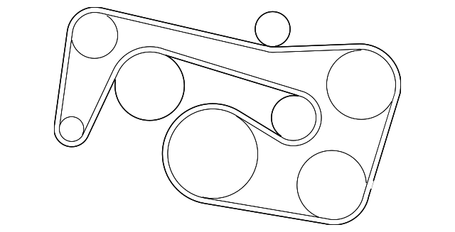
Understanding the Serpentine Belt Diagram Symbols
The serpentine belt diagram is a symbolic representation of the physical system. Here’s a breakdown of common symbols you'll encounter:
- Solid Lines: Represent the serpentine belt itself. The line's thickness may vary slightly but is primarily a visual aid.
- Circles: Indicate pulleys. The size of the circle doesn't necessarily reflect the actual size of the pulley. Often, different circle types indicate driven vs. idler pulleys.
- Arrows: Indicate the direction of belt rotation. This is crucial for proper routing. Make sure the belt follows the arrows correctly.
- Labels: Pulleys are typically labeled with abbreviations indicating their function (e.g., "ALT" for alternator, "P/S" for power steering, "A/C" for air conditioning, "CRANK" for crankshaft, "TENS" for tensioner, "IDLER" for idler).
- Dashed Lines (Sometimes): Occasionally, dashed lines might be used to indicate the belt's path behind other components for clarity.
- Tensioner Symbol: The tensioner is often represented with a specific symbol that includes an arrow indicating the direction of spring tension.
Color coding isn't generally used in standard serpentine belt diagrams, but if you encounter a diagram with colors, it's essential to refer to the diagram's legend for explanation.
How the Serpentine Belt System Works
The engine's crankshaft provides the power source. As the crankshaft rotates, it turns the crankshaft pulley. This pulley then drives the serpentine belt, which in turn drives all the other accessory pulleys. The tensioner pulley maintains the proper tension on the belt, preventing slippage and ensuring efficient power transfer. The idler pulleys guide the belt along the correct path, maximizing the contact area between the belt and the driven pulleys. Proper belt tension is paramount. Too little tension, and the belt will slip, leading to reduced performance of the accessories. Too much tension, and you risk damaging the belt, pulleys, or even the accessory components themselves.
Real-World Use: Basic Troubleshooting Tips
Here are some common problems you might encounter and how the diagram can help:
- Squealing Belt: This is often caused by a loose belt, worn belt, or a glazed pulley. Use the diagram to check the belt's tension and condition. Inspect the pulleys for signs of damage or glazing. Pay close attention to the tensioner; a weak or failing tensioner can cause belt slippage and noise.
- Belt Slippage: Symptoms include dimming headlights, reduced power steering assist, or poor air conditioning performance. Check the belt tension and condition. Also, inspect the pulleys for signs of oil or coolant contamination, which can reduce friction between the belt and pulleys. The diagram will help you locate and inspect all pulleys.
- Belt Breakage: A broken belt can be caused by a number of factors, including age, wear, misalignment, or a seized pulley. Use the diagram to trace the belt's path and identify any potential sources of binding or obstruction. Replace the belt and address any underlying issues.
- Visual Inspection: Regularly inspect the belt for cracks, fraying, missing ribs, or other signs of damage. Compare the belt's position to the diagram to ensure it's properly routed.
If you suspect a problem, use the diagram to visually confirm the belt is routed correctly, then inspect the belt and each pulley for any signs of wear, damage, or misalignment. Don't ignore unusual noises or performance issues; they could be early warning signs of a more significant problem.
Safety Considerations
Working around the serpentine belt system can be dangerous if you're not careful. Here are some key safety precautions:
- Disconnect the Negative Battery Terminal: Before working on any part of the engine, always disconnect the negative battery terminal to prevent accidental electrical shock.
- Ensure the Engine is Cool: Never work on the serpentine belt system while the engine is hot. Allow the engine to cool completely to avoid burns.
- Keep Hands and Clothing Clear: Never insert your hands or clothing near the serpentine belt while the engine is running. The belt can quickly pull you in, causing serious injury.
- Wear Safety Glasses: Protect your eyes from debris and fluids.
- Use the Correct Tools: Use the appropriate tools for the job, such as a belt tensioner tool, to avoid damaging components or injuring yourself.
- Be Aware of Rotating Parts: Even with the engine off, some components may still rotate slightly. Be mindful of this and keep your hands clear.
The area around the crankshaft pulley is particularly risky due to its close proximity to the engine and its high rotational speed. Exercise extreme caution when working in this area.
Remember, if you're not comfortable performing any of these tasks yourself, it's always best to consult a qualified mechanic.
To help you even further, we have the detailed 2013 Mercedes C250 Serpentine Belt Diagram readily available. You can download it and keep it handy for any future maintenance or repair needs related to your belt system. This detailed diagram will be an invaluable resource for confidently tackling your C250's belt-related issues.