2013 Nissan Altima Belt Diagram With Electric Power Steering
Alright folks, let's dive into the serpentine belt system of the 2013 Nissan Altima, specifically models equipped with Electric Power Steering (EPS). Understanding this system is crucial for a variety of reasons, from preventative maintenance to tackling common issues like belt squeal or component failure. This article aims to provide a clear, detailed explanation to help you confidently diagnose and repair this vital part of your vehicle.
Purpose of the Diagram
The serpentine belt diagram is your roadmap to understanding the layout of the belt drive system. It’s essential for several reasons:
- Correct Belt Routing: The most obvious purpose is ensuring the serpentine belt is routed correctly around all pulleys. Incorrect routing can lead to component failure, reduced performance, and even engine damage.
- Troubleshooting: The diagram allows you to visually inspect the system and identify potential problem areas, such as misaligned pulleys or damaged components.
- Component Identification: You can easily identify each component driven by the belt, like the alternator, power steering pump (in this case, EPS motor), AC compressor, and water pump.
- Repair and Replacement: When replacing the belt or any of the driven components, the diagram provides a reference for proper installation and tensioning.
Key Specs and Main Parts
The 2013 Nissan Altima with EPS typically uses a single, long serpentine belt to drive all the accessories. The length and specific part number of the belt can vary slightly depending on the engine (2.5L or 3.5L), so always double-check your vehicle's specifications. Look for the belt diagram sticker usually located under the hood or in the engine compartment. Let's look at the main components involved:
- Crankshaft Pulley (Harmonic Balancer): This pulley, attached to the crankshaft, is the driving force behind the entire system. It's responsible for transferring engine power to the serpentine belt.
- Alternator Pulley: The alternator converts mechanical energy from the engine into electrical energy to power the vehicle's electrical system and charge the battery.
- AC Compressor Pulley: The AC compressor is responsible for compressing the refrigerant in the air conditioning system.
- Water Pump Pulley: The water pump circulates coolant throughout the engine to regulate its temperature.
- Tensioner Pulley: This spring-loaded pulley maintains the correct tension on the serpentine belt. It is critical for optimal performance and belt longevity.
- Idler Pulley(s): These pulleys provide guidance and support to the serpentine belt, especially on longer spans between driven components. The number of idler pulleys will depend on the engine and accessory configuration.
- EPS Motor (Electric Power Steering): Instead of a traditional hydraulic power steering pump driven by the belt, the 2013 Altima with EPS uses an electric motor to provide power steering assistance. This motor typically interfaces directly with the steering rack and is not driven by the serpentine belt. Therefore, it won't appear on a belt diagram. The belt would route directly around the other components, bypassing the space a hydraulic pump would normally occupy.
Symbols: Understanding the Diagram
Serpentine belt diagrams use specific symbols to represent different components and their relationship to the belt. Here's a breakdown:
- Solid Lines: A solid line represents the path of the serpentine belt.
- Arrows: Arrows indicate the direction of belt travel. It’s critical to follow the arrow's directions for proper routing.
- Circles: Circles represent pulleys. The size of the circle generally does *not* indicate the actual size of the pulley.
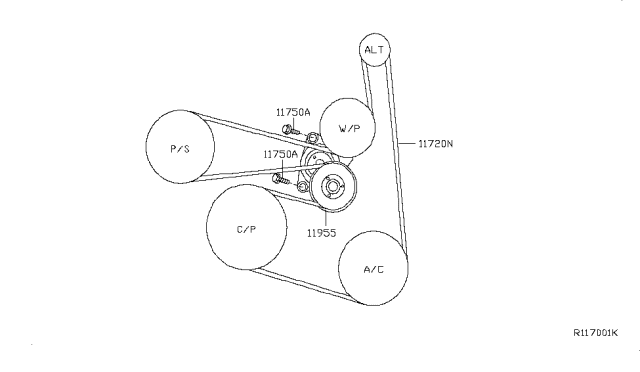
- Component Labels: Each pulley will be labeled with an abbreviation (e.g., ALT for Alternator, AC for AC Compressor, WP for Water Pump, CRK for Crankshaft).
- Tensioner Symbol: The tensioner pulley is often depicted with a spring symbol, indicating its spring-loaded mechanism.
- Ribbed vs. Smooth Pulleys: Some diagrams will differentiate between ribbed and smooth pulleys. The ribbed side of the belt must always contact ribbed pulleys, and the smooth side must contact smooth pulleys.
How It Works
The crankshaft pulley, driven by the engine's rotation, turns the serpentine belt. This belt then transfers rotational energy to each of the driven components: alternator, AC compressor, and water pump. The tensioner pulley applies constant pressure to the belt, ensuring it maintains sufficient grip on each pulley to prevent slippage. As mentioned earlier, the EPS motor is electrically powered and not directly driven by the serpentine belt; therefore, the belt configuration is simplified by omitting the hydraulic pump.
Real-World Use: Basic Troubleshooting
Here are some common issues you might encounter and how the diagram can help you diagnose them:
- Belt Squeal: A squealing belt often indicates insufficient tension. Check the tensioner pulley for proper operation. Also, inspect the belt for cracks, glazing, or wear. The diagram helps you visually inspect the entire belt run for potential problems.
- Component Failure: If a component, like the alternator, fails, the belt may stop turning that pulley, causing other issues. The diagram helps you identify which component is malfunctioning.
- Belt Slipping: Slipping can occur due to a worn belt, contaminated pulleys (oil or coolant), or excessive load on one of the driven components. Inspect the belt and pulleys for contaminants, and ensure the tensioner is functioning correctly. The diagram highlights the locations of pulleys prone to contamination.
- Belt Breaking: A broken belt can be caused by a number of factors, including age, wear, misalignment, or a seized component. Inspect all pulleys for free rotation. The diagram helps trace the belt's path to identify potential points of stress.
Safety: Risky Components
Working on the serpentine belt system can be dangerous if proper precautions are not taken. Here are some key safety considerations:
- Engine Off: Always ensure the engine is turned off and the key is removed from the ignition before working on the serpentine belt system.
- Battery Disconnect: Disconnecting the negative battery cable is highly recommended to prevent accidental starting of the engine.
- Hot Components: Be aware that engine components, especially the exhaust manifold, can remain hot for some time after the engine is turned off. Allow sufficient time for cooling before working in the engine bay.
- Moving Parts: Keep hands, clothing, and tools clear of the serpentine belt and pulleys when the engine is running.
- Tensioner Spring: The tensioner pulley is spring-loaded and can snap back forcefully when released. Use the appropriate tool to relieve tension safely. Never attempt to release the tensioner without the proper tools.
Electric Power Steering Considerations
Even though the EPS system isn't directly related to the belt, be aware that its high-voltage components can pose an electrical shock hazard. Disconnecting the battery is an absolute must before working near the steering rack or EPS motor assembly. Refer to the vehicle's service manual for specific instructions on safely servicing the EPS system.
Understanding the serpentine belt diagram is a fundamental skill for any DIY mechanic. It enables you to perform basic maintenance, troubleshoot common issues, and replace components with confidence. By following the safety guidelines outlined above, you can work on this system safely and effectively.
For a printable version of the 2013 Nissan Altima Belt Diagram with Electric Power Steering, you can download the file here: [Download Link Placeholder - We have the file].