
2013 Nissan Frontier Fuse Box Diagram
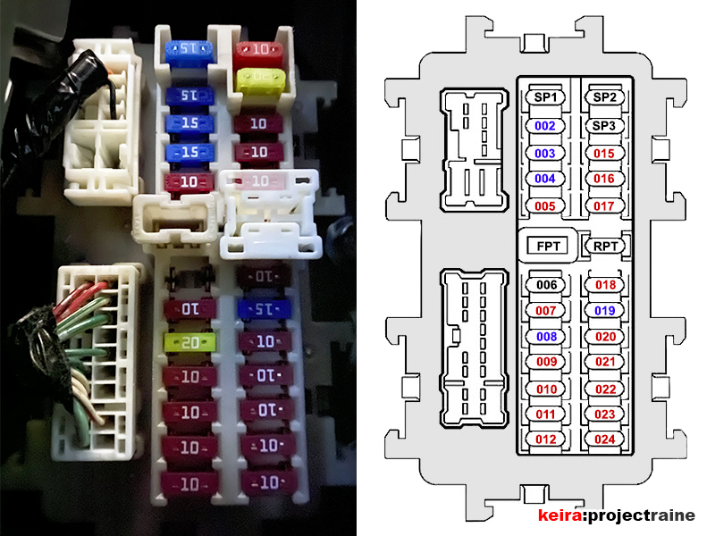
Alright folks, let's dive into the fuse box diagram for the 2013 Nissan Frontier. If you're like me, you believe in getting your hands dirty and understanding how your vehicle ticks. This guide will break down everything you need to know about the 2013 Frontier's fuse box layout, from identifying individual fuses to understanding the circuits they protect. Consider this your go-to resource for troubleshooting electrical issues, planning modifications, or simply gaining a deeper understanding of your truck's electrical system.
Purpose of Understanding the Fuse Box Diagram
Why bother learning about the fuse box? Well, the most obvious reason is for repairs. When something electrical malfunctions in your Frontier, a blown fuse is often the culprit. Knowing the diagram lets you quickly identify the faulty fuse, replace it, and get back on the road. Beyond that, understanding the fuse box is invaluable for:
- Troubleshooting Electrical Problems: Tracing circuits to isolate faults.
- Planning Modifications: Safely tapping into power for accessories like lights, winches, or aftermarket stereos.
- General Maintenance: Knowing your vehicle's systems.
- Preventing Further Damage: Replacing a fuse with the correct amperage prevents overloading and potential fires.
Key Specs and Main Parts of the 2013 Frontier Fuse Box
The 2013 Nissan Frontier, like most vehicles, has multiple fuse boxes. We're going to focus on two primary locations:
- Interior Fuse Box: Located inside the cabin, usually under the dashboard on the driver's side. This protects circuits related to interior functions like the radio, power windows, dome lights, and instrument panel.
- Engine Compartment Fuse Box (IPDM E/R): Situated in the engine bay, often near the battery. This handles circuits for critical engine components, headlights, the cooling fan, and other high-power systems. The IPDM E/R, or Intelligent Power Distribution Module Engine Room, is essentially a sophisticated fuse box with some relay functions built in.
Each fuse box contains several components:
- Fuses: These are the sacrificial links in the electrical chain, designed to break the circuit when excessive current flows. They come in various amperage ratings (measured in Amperes or Amps, denoted by "A"). The diagram will specify the correct amperage for each fuse location. Common types are blade fuses (ATO/ATC) and mini-blade fuses.
- Relays: Electrically operated switches that control high-current circuits using a low-current signal. They're used for components like headlights, horns, and the starter motor.
- Circuit Breakers: These automatically interrupt the electrical circuit if overloaded, but unlike fuses, they can be reset and reused.
- Fuse Puller: A small plastic tool used to safely remove fuses without damaging them or the fuse box.
Understanding Fuse Box Symbols
Fuse box diagrams use symbols to represent different components and circuits. While the exact symbols can vary slightly, here are some common ones you'll encounter:
- Lines: Indicate electrical wires and connections. Thicker lines may represent higher-current circuits.
- Rectangles/Squares with a Number Inside: Typically represent fuses. The number inside indicates the amperage rating of the fuse (e.g., "10" means a 10-Amp fuse).
- Circles/Ovals: Can represent various components, sometimes with a letter code inside indicating the component type (e.g., "H" for horn, "L" for lights).
- Relay Symbols: Usually depicted as a coil with a switch. The coil represents the relay's electromagnet, and the switch represents the contacts that open or close the circuit.
- Color Coding: While not always present *on* the fuse box itself, some diagrams use color coding to indicate the amperage rating of the fuse (e.g., yellow for 20A, blue for 15A). It is VERY important to use fuses with the specified amperage. Never substitute a higher amperage fuse in place of a lower amperage fuse. This can cause damage to components and create a fire hazard.
How the Fuse Box Works
The fuse box is essentially a distribution point for electrical power throughout the vehicle. Power from the battery flows to the fuse box, and from there, it's distributed to various circuits, each protected by a fuse or circuit breaker. When a short circuit or overload occurs (too much current flowing through the circuit), the fuse's internal element melts, breaking the circuit and preventing damage to other components. Think of it like a dam – the fuse is designed to fail before the more important (and expensive) systems do.
Relays, on the other hand, act as remote-controlled switches. The vehicle's control system (e.g., the BCM – Body Control Module) sends a small electrical signal to the relay's coil, which then activates the switch, allowing a larger current to flow through the circuit to power the intended device.
Real-World Use: Basic Troubleshooting Tips
Let's say your 2013 Frontier's radio suddenly stops working. Here's how you might use the fuse box diagram to troubleshoot:
- Consult the Diagram: Locate the interior fuse box diagram (usually in your owner's manual or available online – *we have a downloadable version for you*).
- Identify the Radio Fuse: Find the fuse labeled for the radio. The diagram will tell you its location and amperage rating.
- Inspect the Fuse: Use the fuse puller to remove the fuse. Examine it closely. If the small wire inside the fuse is broken or blackened, the fuse is blown.
- Replace the Fuse: Replace the blown fuse with a new fuse of the *exact same* amperage rating.
- Test the Radio: Turn on the radio to see if it now works. If it does, you've solved the problem.
- If the Fuse Blows Again: If the new fuse blows immediately or shortly after replacement, there's a short circuit in the radio circuit. This requires further investigation, potentially involving checking the wiring and the radio itself. Do not continue to replace fuses without addressing the underlying issue.
Important Considerations:
- Always turn off the ignition before working on the electrical system.
- Never replace a fuse with one of a higher amperage rating. This can overload the circuit and cause a fire.
- If you're unsure about any step, consult a qualified mechanic. Electrical problems can be complex and dangerous.
Safety Considerations
Working with your vehicle's electrical system requires caution. Here are some key safety points:
- Disconnect the Battery: For major electrical work, disconnect the negative battery terminal to prevent accidental shorts.
- High-Voltage Components: Be extremely careful around components like the ignition coil and the alternator. These can generate high voltages that can be dangerous.
- Airbag System: The airbag system is also electrically controlled. If you're working near airbags, consult the service manual for proper procedures to disable them safely. Improper handling can cause accidental airbag deployment, which can be harmful.
- Proper Tools: Use insulated tools when working with electrical components.
Working on the electrical system always comes with risks. If you are not comfortable with electrical diagnostics, consult a professional mechanic.
Now you know how to analyze your 2013 Nissan Frontier Fuse Box Diagram.
We have the full, high-resolution 2013 Nissan Frontier Fuse Box Diagram available for download! You can download it below.
[Download Link Here - Placeholder]