2013 Nissan Juke Fuse Box Diagram
The 2013 Nissan Juke, with its distinctive styling and turbocharged engine, is a popular choice for drivers looking for something a little different. However, like all vehicles, it relies heavily on its electrical system for proper operation. Understanding the fuse box diagram is crucial for diagnosing and resolving electrical issues, performing modifications, or simply gaining a better understanding of your Juke's inner workings. This article will serve as a detailed guide to the 2013 Nissan Juke fuse box diagram, helping you navigate its complexities with confidence.
Purpose of Understanding the Fuse Box Diagram
The fuse box diagram isn't just a schematic; it's a roadmap to your vehicle's electrical health. Its primary purpose is to identify which fuse protects which circuit. Knowing this allows you to:
- Diagnose Electrical Problems: If a component like a headlight, radio, or power window stops working, the fuse box diagram helps you quickly identify and check the corresponding fuse.
- Perform Repairs: Identifying the correct fuse prevents you from inadvertently damaging other circuits while troubleshooting.
- Install Aftermarket Accessories: When adding new electrical components (like a new sound system or lights), the diagram helps you find appropriate power sources and ensure proper fuse protection.
- Learn About Your Vehicle's Electrical System: Studying the diagram provides a valuable insight into how different systems are powered and protected, improving your overall understanding of automotive electrical systems.
Key Specs and Main Parts of the Fuse Box
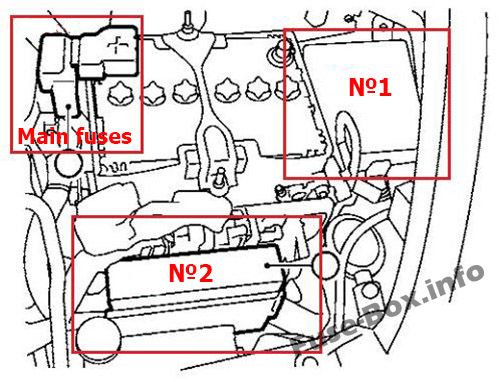
The 2013 Nissan Juke typically has two main fuse box locations:
- Interior Fuse Box: Located under the dashboard on the driver's side (often behind a small access panel). This fuse box primarily handles circuits related to interior components like lights, the radio, power windows, and the climate control system.
- Engine Compartment Fuse Box: Located in the engine bay, often near the battery. This fuse box houses fuses and relays for critical engine management systems, headlights, and other high-current components.
Key specs to note typically involve the amperage (A) rating of each fuse. This rating indicates the maximum current the fuse can handle before it blows, protecting the circuit from overloads. Fuses come in various amperage ratings, typically ranging from 5A to 30A or higher. Using the correct amperage rating is crucial; using a higher-rated fuse can damage the circuit it's supposed to protect, while a lower-rated fuse will blow prematurely.
Main parts within the fuse box include:
- Fuses: These are the sacrificial components that protect the circuits. They contain a thin wire that melts and breaks the circuit when excessive current flows through them.
- Relays: Relays are electromechanical switches that allow a low-current circuit to control a high-current circuit. They're often used for components that draw a lot of power, like headlights or the starter motor.
- Fuse Puller: A small plastic tool designed to safely remove fuses without damaging them or yourself.
Understanding Fuse Box Symbols
Fuse box diagrams use a combination of lines, colors, and icons to represent different components and circuits. Understanding these symbols is key to interpreting the diagram correctly.
- Lines: Lines represent wires and electrical connections. Thicker lines often indicate higher-current wires.
- Colors: Wire colors are often indicated on the diagram (e.g., "BLU" for blue, "RED" for red, "BLK" for black). Color coding helps identify the correct wire in the vehicle.
- Icons: Icons represent the components protected by each fuse. Common icons include:
- Headlight: A stylized headlight symbol.
- Radio: A radio or speaker symbol.
- Window: A window outline.
- Wiper: A windshield wiper symbol.
- Horn: A horn symbol.
- Engine Control Module (ECM): Often abbreviated as "ECM" or represented by a computer chip symbol.
- Amperage Rating: Each fuse will have a number indicating its amperage rating (e.g., "10A" for 10 amps). This is critical when replacing a blown fuse.
The diagram will also indicate the fuse's position within the fuse box, typically using a grid system (e.g., "A1," "B3"). This allows you to quickly locate the correct fuse.
How the Fuse Box Works
The fuse box acts as a central distribution point for electrical power within the vehicle. Power from the battery flows through the main power cables to the fuse box. From there, it's distributed to various circuits, each protected by a fuse. Each circuit is designed to power a specific component or system. When a circuit experiences an overload (e.g., due to a short circuit or a malfunctioning component), the fuse's thin wire heats up and melts, breaking the circuit and preventing damage to other components. This is a simple but effective way to protect the vehicle's electrical system.
Relays, on the other hand, use a small amount of electrical current to control a circuit carrying a large amount of current. For example, your headlight switch might only handle a small amount of current, but it controls a relay that switches on the headlights, which require a much larger current. Relays prevent excessive current from flowing through the switch, protecting it from damage.
Real-World Use: Basic Troubleshooting Tips
Here's how to use the fuse box diagram to troubleshoot common electrical problems:
- Identify the Problem: Determine which component isn't working (e.g., the radio).
- Consult the Diagram: Locate the fuse corresponding to the non-working component in the appropriate fuse box diagram (interior or engine compartment).
- Inspect the Fuse: Visually inspect the fuse. A blown fuse will typically have a broken filament inside. You can also use a multimeter to check for continuity across the fuse. A working fuse will have continuity (a reading of 0 ohms or close to it). A blown fuse will have no continuity.
- Replace the Fuse: If the fuse is blown, replace it with a new fuse of the same amperage rating.
- Test the Component: After replacing the fuse, test the component to see if it's working again.
- If the Fuse Blows Again: If the new fuse blows immediately or shortly after replacement, there's likely a more serious problem in the circuit, such as a short circuit or a faulty component. Further diagnosis is needed, and you may need to consult a qualified mechanic.
Safety Considerations
Working with automotive electrical systems can be dangerous. Here are some safety precautions:
- Disconnect the Battery: Before working on any electrical components, disconnect the negative terminal of the battery to prevent accidental shocks or short circuits.
- Use Proper Tools: Use insulated tools to avoid electric shock.
- Never Replace a Fuse with a Higher Amperage Rating: This can damage the circuit and potentially cause a fire. Always use the correct amperage rating.
- Be Careful Around Relays: Relays can contain stored energy, even after the battery is disconnected. Avoid touching the terminals unless you're sure they're discharged.
- High-Current Components: Be especially cautious around components like the starter motor and alternator, as they carry extremely high currents and can cause serious injury or death if mishandled.
If you're unsure about any aspect of electrical repair, it's always best to consult a qualified mechanic. They have the training, experience, and tools to diagnose and repair electrical problems safely and effectively.
We have a downloadable version of the 2013 Nissan Juke fuse box diagram available for your convenience. Feel free to download it for future reference. This diagram will be invaluable as you maintain, repair, and even customize your Juke!