2013 Nissan Maxima Fuse Box Diagram
Alright, let's dive into the fuse box diagram for the 2013 Nissan Maxima. This is a crucial piece of information whether you're troubleshooting a malfunctioning component, adding aftermarket accessories, or simply trying to understand your car's electrical system. Understanding the fuse box allows you to diagnose issues efficiently and often fix them yourself, saving you time and money.
Purpose of the 2013 Nissan Maxima Fuse Box Diagram
The fuse box diagram serves as a roadmap to your car's electrical system. It tells you the location of each fuse and relay, and, most importantly, which circuit each one protects. This is vital for:
- Troubleshooting electrical issues: If a specific component like your radio, headlights, or power windows stops working, the diagram helps you quickly identify the corresponding fuse.
- Adding aftermarket accessories: When installing new equipment like amplifiers, lights, or a remote starter, the diagram helps you find suitable power sources and properly fuse the new circuit.
- Understanding your vehicle's electrical system: Even if everything is working perfectly, studying the diagram can give you a better understanding of how your car's electrical components are connected and protected.
- Preventing further damage: Replacing a blown fuse with one of the correct amperage will prevent electrical overloads that could damage sensitive components.
Key Specs and Main Parts
The 2013 Nissan Maxima typically has at least two fuse box locations:
- Interior Fuse Box: Usually located under the dashboard, on the driver's side. This fuse box primarily protects interior components like the radio, power windows, lights, and climate control.
- Engine Compartment Fuse Box: Situated in the engine bay, often near the battery. This fuse box handles the more demanding circuits, such as the engine control unit (ECU), starter motor, headlights, and anti-lock braking system (ABS).
Within each fuse box, you'll find the following main parts:
- Fuses: These are sacrificial devices designed to break an electrical circuit if the current exceeds a safe level. They come in various amperage ratings, indicated by the number printed on them (e.g., 5A, 10A, 15A, 20A, 30A).
- Relays: These are electromagnetic switches used to control high-current circuits using a low-current signal. They're often used for components like headlights, horns, and fuel pumps.
- Fuse Puller: A small plastic tool used to safely remove and insert fuses. Many fuse boxes have one integrated into the cover.
- The Diagram Itself: Typically printed on the inside of the fuse box cover or in the owner's manual. This diagram is your key to understanding the fuse layout.
Symbols and Diagram Interpretation
Understanding the symbols used in the fuse box diagram is crucial. Here's a breakdown:
- Fuses: Fuses are usually represented by a rectangular box with a number indicating the amperage rating (e.g., "10A" for a 10-amp fuse).
- Relays: Relays are often depicted as a square or rectangular box with a coil symbol inside, sometimes with a pin diagram.
- Lines: Solid lines indicate a direct electrical connection. Dashed lines might represent a less direct or conditional connection.
- Colors (Sometimes): While not always present, color-coding can be used to distinguish different circuit types (e.g., red for ignition, blue for lights).
- Icons: Icons are frequently used to represent the component that a fuse protects. For example:
- A lightbulb icon for headlights.
- A speaker icon for the radio.
- A fan icon for the climate control blower motor.
- An engine icon for engine management systems.
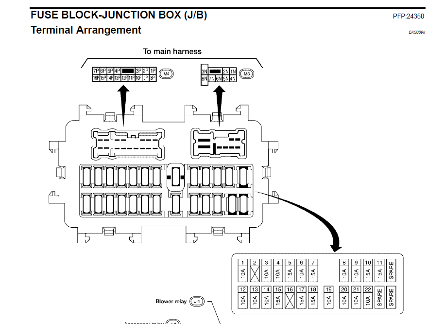
The diagram will also list the component or system protected by each fuse, along with its amperage rating. For example, "Headlight (LH) 15A" means the left headlight is protected by a 15-amp fuse.
Understanding the amperage rating is crucial. Never replace a fuse with one of a higher amperage. Doing so bypasses the circuit protection and can lead to overheating, damage, and even a fire.
How It Works: The Electrical Circuit
To fully grasp the function of fuses, you need a basic understanding of how electrical circuits work in your car.
Every electrical component in your car is part of a circuit that includes a power source (the battery), wiring, a switch (to turn the component on and off), the component itself (e.g., a headlight bulb), and a ground connection. The fuse is placed in this circuit to protect it from overcurrent.
When the circuit operates normally, the current flows through the fuse without interruption. However, if there's a short circuit (a low-resistance path that allows excessive current to flow) or if a component draws too much current, the fuse will heat up and its internal filament will melt, breaking the circuit and stopping the flow of electricity. This prevents damage to the wiring and components.
Relays act as switches. A low-current circuit, activated by a switch on your dashboard (e.g., the headlight switch), energizes the relay's coil. This creates an electromagnetic field that pulls a contact closed, completing a separate, high-current circuit that powers the headlights themselves. This prevents the headlight switch from having to handle the large current required by the headlights, protecting it from damage.
Real-World Use: Basic Troubleshooting Tips
Here's how to use the fuse box diagram for basic troubleshooting:
- Identify the problem: Determine which component is not working (e.g., the radio, a turn signal, etc.).
- Consult the diagram: Locate the fuse that corresponds to the malfunctioning component in the fuse box diagram.
- Locate the fuse: Find the physical fuse in the fuse box based on the diagram.
- Inspect the fuse: Remove the fuse using the fuse puller. Look closely at the filament inside the fuse. If the filament is broken or blackened, the fuse is blown and needs to be replaced.
- Replace the fuse: Replace the blown fuse with a new fuse of the same amperage rating. Never use a fuse with a higher amperage.
- Test the component: Turn on the component to see if it now works.
If the new fuse blows immediately after being replaced, it indicates a persistent short circuit in the wiring or within the component itself. Further diagnosis is required to identify and fix the root cause of the short before replacing the fuse again.
If the component still doesn't work after replacing the fuse, the problem may lie elsewhere, such as in the wiring, the switch, or the component itself. You may need to use a multimeter to test for voltage and continuity in the circuit.
Safety Precautions
Working with your car's electrical system can be dangerous. Always take the following precautions:
- Disconnect the battery: Before working on any electrical components, disconnect the negative terminal of the battery to prevent accidental shocks or shorts. This is especially important when working near the engine compartment fuse box, which is close to the battery.
- Use the right tools: Use a fuse puller to remove and insert fuses. Never use metal objects like screwdrivers, as they can cause shorts.
- Never bypass a fuse: Never replace a fuse with a piece of wire or other conductive material. This bypasses the circuit protection and can lead to serious damage or fire.
- Be aware of high-current components: Components like the starter motor, alternator, and ABS system use high currents. Be extra cautious when working near these components. Consider having a professional diagnose problems with these systems.
- If in doubt, consult a professional: If you're not comfortable working on your car's electrical system, or if you're unsure about any procedure, consult a qualified mechanic.
Remember, safety is paramount. Take your time, follow the instructions carefully, and don't hesitate to seek professional help if needed.
To assist you with this task, we have the 2013 Nissan Maxima fuse box diagram available for download. This detailed diagram will be a valuable resource as you work on your vehicle.