2013 Nissan Rogue Fuse Box Diagram
The 2013 Nissan Rogue, a popular compact SUV, relies heavily on its electrical system for everything from starting the engine to powering the infotainment system. Understanding the fuse box diagram is crucial for diagnosing and resolving electrical issues, performing modifications, or simply gaining a deeper understanding of your vehicle's inner workings. This article serves as a comprehensive guide to the 2013 Nissan Rogue fuse box diagram, providing you with the knowledge needed to confidently tackle electrical projects and repairs.
Purpose of Understanding the Fuse Box Diagram
Why bother with a fuse box diagram? The primary reason is troubleshooting electrical problems. When a circuit malfunctions, the fuse is designed to blow, protecting the more expensive components. The fuse box diagram identifies which fuse corresponds to which circuit. Additionally, the diagram is invaluable for:
- Locating a blown fuse: Quickly identifying and replacing a blown fuse saves time and prevents further damage.
- Performing electrical modifications: When adding aftermarket accessories like lights or a new stereo, understanding the fuse box allows you to tap into the correct power source safely.
- Understanding vehicle systems: Studying the diagram provides a deeper understanding of how different electrical components are interconnected within the vehicle.
- Avoiding costly repairs: Simple electrical issues can often be resolved by replacing a fuse, saving you a trip to the mechanic.
Key Specs and Main Parts
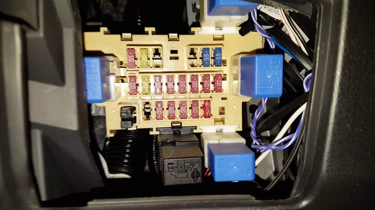
The 2013 Nissan Rogue typically has two main fuse boxes: one located in the engine compartment and another located inside the vehicle, often near the driver's side dashboard. The engine compartment fuse box generally houses fuses for critical systems like the engine control unit (ECU), fuel pump, and headlights. The interior fuse box handles circuits for accessories like the radio, power windows, and interior lights.
Here's a breakdown of the key components:
- Fuse Box Housing: This is the physical container that holds all the fuses and relays. It's usually made of durable plastic and protects the electrical components from the elements.
- Fuses: These are the sacrificial components designed to protect circuits from overcurrent. They come in various amperages, indicated by their color and the number printed on them (e.g., 5A, 10A, 20A).
- Relays: Relays are electromechanical switches that control high-current circuits using a low-current signal. They are often used for components like the headlights, horn, and starter motor.
- Fuse Puller: A small plastic tool designed to safely remove fuses from the fuse box.
- Diagram Label: This is usually a sticker located inside the fuse box cover that illustrates the layout of the fuses and relays, along with their corresponding circuit descriptions. This is the most crucial element.
Symbols, Lines, Colors, and Icons Explained
Understanding the symbols, lines, colors, and icons used in the fuse box diagram is essential for accurate interpretation.
- Lines: Lines represent the electrical circuits. A thicker line might indicate a higher current-carrying capacity.
- Colors: Fuse colors typically correspond to their amperage rating. While not universally standardized, some common color codes include:
- Yellow: 20A
- Blue: 15A
- Red: 10A
- Brown: 7.5A
- Orange: 5A
- Icons: Icons represent the different components or systems that the fuse protects. Common icons include:
- Headlight: Headlight circuit
- Radio: Audio system circuit
- Windshield Wiper: Windshield wiper motor circuit
- Cigarette Lighter/Power Outlet: Accessory power circuit
- ECU: Engine Control Unit circuit
- Numbers: Numbers on the diagram usually correspond to the fuse or relay number within the fuse box. This helps you quickly locate the correct component.
The diagram will also typically show the amperage rating of each fuse, denoted by a number followed by "A" (e.g., 10A). This indicates the maximum current that the fuse can handle before blowing.
How It Works: The Electrical System and Fuses
The electrical system in your 2013 Nissan Rogue is a complex network of wires, circuits, and components. The battery provides the power, and the alternator recharges the battery while the engine is running. Fuses are placed in each circuit to protect the components from damage due to overcurrent or short circuits.
When a circuit experiences an overcurrent condition (e.g., due to a short circuit or a faulty component), the fuse wire melts, breaking the circuit and stopping the flow of electricity. This prevents the overcurrent from reaching and damaging the more expensive components connected to that circuit.
Think of a fuse as a weak link in a chain. It's designed to break first, sacrificing itself to protect the rest of the system. When a fuse blows, it's a sign that there's a problem in the circuit that needs to be addressed.
Real-World Use: Basic Troubleshooting Tips
Here are some basic troubleshooting tips using the fuse box diagram:
- Identify the Problem: Determine which component or system is not working.
- Consult the Diagram: Use the fuse box diagram to identify the fuse associated with the malfunctioning component.
- Locate the Fuse: Open the appropriate fuse box and locate the fuse identified in the diagram.
- Inspect the Fuse: Visually inspect the fuse. A blown fuse will typically have a broken filament or a blackened appearance.
- Test the Fuse (Recommended): Use a multimeter to test the fuse for continuity. A good fuse will show continuity (a reading close to 0 ohms), while a blown fuse will show no continuity (an open circuit).
- Replace the Fuse: If the fuse is blown, replace it with a new fuse of the same amperage rating. Never use a fuse with a higher amperage rating, as this could damage the circuit.
- Test the System: After replacing the fuse, test the component or system to see if it's working correctly.
- If the Fuse Blows Again: If the new fuse blows immediately or shortly after replacement, it indicates a persistent problem in the circuit. Further diagnosis is required to identify and resolve the underlying issue. This might involve checking the wiring, connectors, and components connected to that circuit.
Safety: Highlighting Risky Components
Working with automotive electrical systems can be dangerous if proper precautions are not taken. Always observe the following safety guidelines:
- Disconnect the Battery: Before working on any electrical component, disconnect the negative terminal of the battery to prevent accidental short circuits.
- Use Proper Tools: Use insulated tools designed for automotive electrical work.
- Never Bypass a Fuse: Bypassing a fuse (e.g., by using a piece of wire) can overload the circuit and cause a fire.
- Replace with the Correct Amperage: Always replace a blown fuse with a fuse of the same amperage rating.
- Consult a Professional: If you are not comfortable working on electrical systems, consult a qualified mechanic. High voltage components like the ignition system can be extremely dangerous.
Specifically, be very careful around the ECU and any components related to the airbag system. Improper handling of these systems can result in serious injury or damage.
We have access to the complete 2013 Nissan Rogue fuse box diagram file. You can download it by [Link to Download - Placeholder, replace with actual link]. This diagram will provide you with the detailed information you need to confidently troubleshoot and repair electrical issues on your vehicle. Remember to always prioritize safety and consult a professional if you're unsure about any aspect of the electrical system.