2013 Nissan Titan Fuse Box Diagram
Alright, let's dive into the 2013 Nissan Titan's fuse box diagram. Understanding this diagram is absolutely crucial whether you're chasing down a simple blown fuse, diagnosing a more complex electrical problem, planning some aftermarket accessory installations, or just trying to get a better grip on your truck's electrical system. I've seen a lot of frustrating electrical problems turn into simple fixes just because someone understood how to read the fuse box diagram. We have the diagram you can download; the link is at the bottom of this article.
Purpose and Importance
Why bother with a fuse box diagram? Well, picture this: your tail lights are out, and it's pitch black. You're probably going to want to avoid getting a ticket, or worse, causing an accident. A quick peek at the fuse diagram, identifying and replacing the blown fuse could get you back on the road safely in minutes. Or say you're installing a new stereo system or auxiliary lighting. Knowing which circuits are already in use and how they're fused helps prevent overloads that can damage your wiring and leave you stranded. Essentially, the fuse box diagram is your electrical roadmap for the Titan. It shows you exactly which fuse protects which circuit, making troubleshooting and modification much easier and safer.
Key Specs and Main Parts of the 2013 Nissan Titan Fuse System
The 2013 Nissan Titan has multiple fuse boxes. The two most important are the Interior Fuse Box and the Engine Compartment Fuse Box.
- Interior Fuse Box: Typically located inside the cabin, often under the dashboard on the driver's side. It houses fuses for circuits like the interior lights, radio, power windows, and other accessories. This is generally your first stop for accessory-related issues.
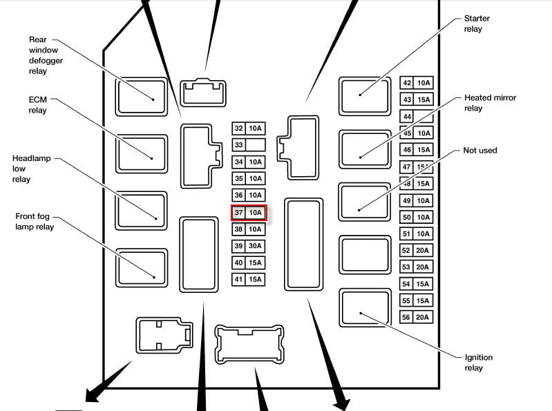
- Engine Compartment Fuse Box: Located under the hood, near the engine, naturally. It protects vital engine components like the fuel pump, ignition system, headlights, and the Electronic Control Module (ECM). This fuse box often has a higher amperage fuses due to the larger loads of the engine and related systems.
Now, let's talk about the components within these boxes:
- Fuses: These are the sacrificial components, designed to break the circuit when the current exceeds a safe level. They come in various amperage ratings (e.g., 5A, 10A, 15A, 20A, 30A), indicated on the fuse itself. The amperage refers to the amount of electrical current a fuse can handle before blowing.
- Relays: These are electromechanical switches that allow a low-current circuit to control a high-current circuit. Think of them as electrical amplifiers. You'll find relays controlling things like the fuel pump, starter motor, and headlights.
- Fusible Links: These are heavier-duty fuses, often used to protect major circuits like the charging system. They are usually located in the engine compartment fuse box. They offer a more robust protection for higher amperage systems.
- The Fuse Box Itself: This holds all the fuses, relays, and fusible links and provides the electrical connections between them and the wiring harness. Most diagrams will have a legend printed on the inside of the fuse box lid, but these can sometimes be damaged or missing, making a downloaded diagram invaluable.
Understanding Fuse Box Symbols
The fuse box diagram isn't just a bunch of random lines and squares. It uses a standardized set of symbols to represent different components and circuits. Here's a breakdown of some common symbols you'll encounter:
- Solid Lines: Represent wires connecting different components.
- Dashed Lines: Usually indicate ground connections. A good ground is *critical* for proper circuit operation.
- Rectangles: Typically represent relays.
- Small Rectangles with a Number Inside: These are the fuses, with the number indicating the amperage rating.
- Icons: Various icons represent the components being protected by the fuse (e.g., a headlight icon for the headlight circuit, a fuel pump icon for the fuel pump circuit). These icons are standardized, but refer to your diagram's legend for specific meaning.
Pay close attention to the legend on the fuse box diagram. It will explain the specific symbols and abbreviations used in your particular diagram. Colors of wires may also be indicated, which can be helpful when tracing wires throughout the truck's electrical system.
How It Works: A Simple Circuit
To really grasp the fuse box diagram, let's break down a simple circuit. Imagine the circuit for your interior dome light. It starts with the battery providing power. The power flows through a wire to the fuse box. Inside the fuse box, a fuse (let's say a 10A fuse) protects the circuit. From the fuse, the power flows to the dome light switch. When you turn the switch on, the power flows through the dome light bulb, causing it to illuminate. Finally, the power returns to the battery through a ground connection, completing the circuit.
If something goes wrong – say, the dome light bulb shorts out – the current flowing through the circuit will dramatically increase. This increased current causes the fuse to blow, breaking the circuit and preventing damage to the wiring and other components. The blown fuse is a visual indication that something is wrong downstream in the circuit.
Real-World Use: Basic Troubleshooting Tips
Okay, so your radio isn't working. Here's how to use the fuse box diagram to troubleshoot:
- Locate the Fuse Box: Determine whether it's likely an interior accessory or engine related, locate the appropriate fuse box.
- Consult the Diagram: Find the fuse that corresponds to the radio circuit. Use the diagram to identify the correct fuse location.
- Inspect the Fuse: Pull the fuse out (use a fuse puller if you have one – they're cheap and prevent you from dropping the fuse in the fuse box). Visually inspect the fuse. If the small wire inside the fuse is broken, the fuse is blown.
- Replace the Fuse: Replace the blown fuse with a new fuse of the *same* amperage rating. Never use a higher amperage fuse – this can overload the circuit and cause a fire.
- Test the Circuit: Turn on the radio. If it works, great! You've fixed the problem. If the new fuse blows immediately, there's a short circuit in the radio wiring or the radio itself. Further troubleshooting is required.
A multimeter can be extremely helpful in electrical troubleshooting. You can use it to check for voltage at the fuse, continuity in the wiring, and resistance in the components. If you are installing an aftermarket accessory, consult the schematic for its wiring harness and fuse requirements, then find an appropriate place to tap into the electrical system with the correct fuse protection. Many add-a-fuse adapters are available from auto parts stores for tapping into existing circuits to power new accessories.
Safety: Highlighting Risky Components
Working with electrical systems can be dangerous. Here are a few safety precautions to keep in mind:
- Disconnect the Battery: Before working on any electrical system, disconnect the negative terminal of the battery. This prevents accidental shorts and potential electrocution.
- Never Bypass a Fuse: Never replace a blown fuse with a wire or a higher amperage fuse. This is a fire hazard. Fuses are designed to protect the circuit; bypassing them removes that protection.
- Work in a Well-Lit Area: Make sure you have adequate lighting to see what you're doing.
- Use the Right Tools: Use insulated tools to prevent accidental shorts.
- Be Careful with Airbags: The airbag system is electrically controlled and can be dangerous if mishandled. Avoid working on any airbag components unless you are properly trained and have the necessary equipment. Incorrect handling of airbags can cause serious injury.
- High-Amperage Fuses: Exercise extreme caution around high-amperage fuses and fusible links. These can deliver a powerful shock.
Always prioritize safety when working on your vehicle's electrical system. If you're not comfortable with electrical work, consult a qualified mechanic. It's better to be safe than sorry.
Remember, the 2013 Nissan Titan fuse box diagram is your key to understanding and troubleshooting your truck's electrical system. Understanding these diagrams makes working on your car easier and safer. It's a valuable tool for any DIYer. Download the diagram below!
Download the 2013 Nissan Titan Fuse Box Diagram: [Link to Downloadable Diagram]