2013 Silverado Radio Wiring Harness Diagram
So, you're diving into the audio system of your 2013 Silverado, huh? Whether you're upgrading the head unit, fixing a blown speaker, or just trying to understand how all those wires behind the dash connect, a solid understanding of the radio wiring harness diagram is absolutely essential. This isn't just about avoiding blown fuses; it's about doing the job right, safely, and efficiently. This article will break down the 2013 Silverado radio wiring harness diagram, explaining its key components, symbols, and how to use it for troubleshooting.
Purpose of the Wiring Harness Diagram
The wiring harness diagram for your 2013 Silverado's radio is essentially a road map to the electrical system that powers your audio. It serves several critical purposes:
- Repairs: When a speaker stops working, the radio cuts out, or you experience other audio-related issues, the diagram allows you to trace the wiring, identify potential breaks or shorts, and pinpoint the faulty component.
- Upgrades: If you're installing a new aftermarket head unit, amplifier, or other audio equipment, the diagram helps you correctly connect the new components to the existing wiring, ensuring proper functionality and preventing damage.
- Learning: Even if you're not currently experiencing problems, understanding the wiring diagram gives you a deeper insight into the electrical system of your vehicle. This knowledge can be invaluable for future troubleshooting and modifications.
- Customization: Want to add a subwoofer or a new set of tweeters? The diagram provides the information you need to tap into the correct wires for power, ground, and signal.
Key Specs and Main Parts
The 2013 Silverado radio wiring harness diagram typically includes the following key specifications and identifies the main components:
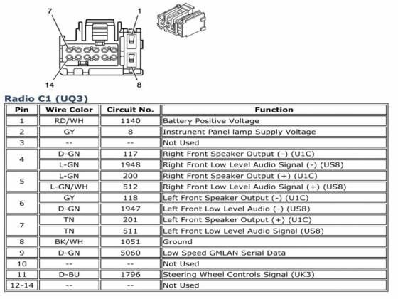
- Wire Colors: Each wire in the harness is identified by a specific color, allowing you to easily distinguish between different circuits. For example, a solid yellow wire might be the constant 12V power supply, while a green wire with a white stripe could be a speaker output.
- Pin Locations: The diagram shows the physical location of each wire within the radio connector (the plug that connects to the back of the radio). This is usually represented by a grid or numbering system.
- Circuit Functions: Each wire is labeled with its specific function, such as "Left Front Speaker (+)", "Ground", "Accessory Power", or "Antenna Trigger".
- Connector Types: The diagram may also identify the type of connector used for the radio and other related components. This information is helpful when purchasing replacement connectors or adapters.
Main parts identified on the diagram include:
- Radio Head Unit: This is the central control unit for the audio system.
- Speakers: The diagram shows the wiring for each speaker (front left, front right, rear left, rear right, and potentially a subwoofer).
- Amplifier (if equipped): Some Silverado models have a factory amplifier. The diagram will show the wiring between the radio and the amplifier.
- Antenna: The antenna wire connects to the radio and receives radio signals.
- Ground Connections: Ground wires provide a return path for the electrical current.
- Power Wires: These wires provide power to the radio. Typically, there are two power wires: a constant 12V wire and an accessory (switched) 12V wire.
Understanding the Symbols
Wiring diagrams use standard symbols to represent electrical components and connections. Here's a breakdown of some common symbols you'll encounter in the 2013 Silverado radio wiring harness diagram:
- Solid Lines: Represent wires. The thickness of the line might sometimes, but not always, indicate wire gauge (thickness). Thicker lines are usually for power or ground.
- Dashed Lines: Often represent shielded cables or less critical connections.
- Colors: As mentioned earlier, colors are crucial for identifying wires. Make sure you have a color key for your specific diagram. Common colors include:
- Red: Typically a fused 12V+ constant power wire.
- Yellow: Usually a 12V+ constant power wire (memory/clock).
- Orange: Often illumination or dimmer wire.
- Black: Always ground.
- Blue: Remote turn-on (for amplifiers).
- Green/White/Gray/Violet: Speaker wires. Usually paired with a matching color with a black stripe to indicate polarity (+/-).
- Circles and Dots: Represent wire splices or connections.
- Rectangles: Usually represent connectors or components like fuses and relays.
- Ground Symbol: Looks like an upside-down triangle or a series of horizontal lines getting shorter.
It's important to consult the specific legend or key provided with your diagram, as symbols can vary slightly between manufacturers.
How It Works
The radio wiring harness works by providing power, ground, and signal connections to the radio head unit and other audio components. Here's a simplified overview:
- Power Supply: The battery provides power to the radio through two main wires: a constant 12V wire (for memory and clock functions) and an accessory (switched) 12V wire (which is only active when the ignition is turned on). These wires are usually protected by fuses.
- Ground Connection: The ground wire provides a return path for the electrical current, ensuring that the radio can operate properly.
- Input Signals: The radio receives input signals from various sources, such as the antenna (for radio broadcasts) and auxiliary inputs (for connecting external devices like smartphones or MP3 players).
- Output Signals: The radio amplifies the input signals and sends them to the speakers through the speaker wires. Each speaker has two wires: a positive (+) wire and a negative (-) wire. Proper polarity is important for optimal sound quality.
- Control Signals: The radio also receives control signals from various sources, such as the steering wheel controls (for adjusting volume, changing channels, etc.) and the vehicle's computer (for displaying information on the radio screen).
Real-World Use – Basic Troubleshooting Tips
Here are some basic troubleshooting tips using the wiring diagram:
- No Power to Radio: Check the fuses first! Use the diagram to identify the fuse that protects the radio circuit. If the fuse is blown, replace it with a new one of the same amperage. If the fuse blows again immediately, there's likely a short circuit in the wiring. Use the diagram to trace the power and ground wires, looking for any signs of damage or corrosion.
- Speaker Not Working: Use the diagram to identify the speaker wires for the affected speaker. Check the wiring for any breaks or loose connections. You can use a multimeter to test the speaker wires for continuity. If the wiring is intact, the speaker itself might be faulty.
- Distorted Sound: Check the speaker wiring for proper polarity. If the positive and negative wires are reversed, it can cause phase cancellation, resulting in distorted sound. Also, check for loose connections or damaged speakers.
- Aftermarket Radio Install Issues: Double-check all your connections against the diagram. Verify that you've connected the correct wires for power, ground, speakers, and any other features you want to use (such as steering wheel controls or a backup camera). Many aftermarket radio installers utilize wiring harness adapters specifically designed for the 2013 Silverado to simplify the installation process.
Safety – Highlight Risky Components
Working with electrical systems can be dangerous. Here are some important safety precautions:
- Disconnect the Battery: Always disconnect the negative battery terminal before working on the electrical system to prevent accidental shorts and shocks. This is absolutely crucial!
- Identify Power Wires: The constant 12V wire is a high-risk component. If it comes into contact with ground, it can cause a short circuit and potentially a fire. Be extremely careful when working with this wire.
- Use Proper Tools: Use insulated tools to prevent electric shock.
- Avoid Working in Wet Conditions: Water and electricity don't mix.
- Double-Check Your Work: Before reconnecting the battery, double-check all your connections to ensure that they are correct and secure.
- When in Doubt, Seek Professional Help: If you're not comfortable working with electrical systems, it's always best to consult a qualified mechanic or electrician.
Remember, you're dealing with the car's electrical system, so exercise caution. Always double-check your connections and never work on the system with the battery connected. This is particularly true when dealing with the constant 12V power wire, which can cause a significant short if mishandled.
Consult the Wiring Diagram: Before beginning any work, make sure to thoroughly review the wiring diagram. This will help you understand the layout of the system and identify the correct wires for your specific task. Accurate identification is key to avoiding mistakes. We have the complete 2013 Silverado radio wiring harness diagram available for download. It's a invaluable resource for any DIY project or repair.