2013 Toyota Corolla Fuse Box Diagram
So, you're diving into the electrical system of your 2013 Toyota Corolla? Excellent choice. Understanding the fuse box diagram is absolutely crucial whether you're troubleshooting a blown fuse, installing aftermarket accessories, or simply trying to get a better handle on your car's inner workings. This article will break down the 2013 Corolla's fuse box diagram in a way that's clear, concise, and actually useful.
Purpose of the Fuse Box Diagram
The fuse box diagram is essentially a roadmap of your car's electrical system. It tells you:
- Which fuse protects which circuit or component.
- The amperage rating (the "size") of each fuse.
- The physical location of each fuse within the fuse box.
Why does this matter? Imagine your headlights suddenly go out. Instead of blindly replacing every bulb, the fuse box diagram allows you to quickly identify and check the headlight fuse. Similarly, if you’re adding a new amplifier, knowing the location of the accessory power fuse is key to a clean and safe installation. Furthermore, studying the diagram helps you to understand how your car's electrical components are connected, aiding in complex troubleshooting scenarios.
Key Specs and Main Parts of the Fuse Box
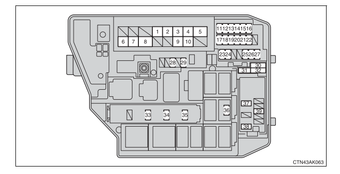
Your 2013 Corolla actually has two main fuse box locations:
- Engine Compartment Fuse Box: Located under the hood, this box houses fuses and relays for high-current components like the headlights, starter motor, cooling fan, and various engine management systems.
- Interior Fuse Box: Typically found under the dashboard, often near the steering wheel, this box protects circuits for interior components like the radio, power windows, cigarette lighter (power outlet), and interior lights.
Within each fuse box, you'll find:
- Fuses: These are the sacrificial components that protect the circuits. They consist of a thin wire that melts and breaks the circuit when excessive current flows through them.
- Relays: Electrically operated switches that allow a low-current circuit to control a high-current circuit. For example, the headlight switch activates a relay that then supplies power to the headlights.
- Fuse Puller: A small plastic tool (usually clipped inside the fuse box cover) used to safely remove fuses. Always use this tool.
- Diagram Label: A sticker, often on the inside of the fuse box cover, illustrating the location and function of each fuse and relay. This is what we're focusing on understanding.
Understanding the Symbols
Fuse box diagrams aren't always perfectly intuitive, but once you understand the basics, they become much easier to decipher. Here's a breakdown of common symbols and conventions:
- Fuse Amperage Rating: This is usually indicated by a number (e.g., 10A, 15A, 20A). This number represents the maximum current (in Amperes) that the fuse can handle before blowing. Never replace a fuse with one of a higher amperage rating, as this can damage the wiring and components in the circuit.
- Fuse Function/Component Name: Each fuse location is typically labeled with a name or abbreviation indicating the component it protects. Examples include "HEAD (LH)" for the left-hand headlight, "RADIO," "WIPER," or "ECU-B."
- Lines and Connections: Lines on the diagram represent wires or electrical pathways. They show how different components are connected within the circuit.
- Colors: While not always present on the diagram itself, the wiring connected to the fuse box will use color-coded wires. Knowing Toyota's typical color codes can be helpful (e.g., blue for headlights, green for turn signals), but always refer to the wiring diagram for definitive information.
- Icons: Some diagrams may use icons to represent components. For example, a lightbulb icon might indicate a lighting circuit, or a fan icon for the cooling fan.
Sometimes, a single fuse can protect multiple components. The diagram will clearly indicate this by listing all the components connected to that fuse.
How It Works: A Simplified Electrical Circuit
To truly understand the fuse box, it's helpful to visualize a basic electrical circuit. Imagine a simple circuit consisting of a battery, a switch, a lightbulb, and a fuse. The battery provides the electrical energy. The switch controls the flow of electricity to the lightbulb. The lightbulb consumes the electricity and emits light. The fuse is placed in the circuit to protect it from overcurrent.
When the switch is closed, electricity flows from the battery, through the fuse, through the lightbulb, and back to the battery. If something goes wrong – for instance, if the wiring shorts to ground – the current will spike dramatically. This excessive current will cause the fuse wire to melt, breaking the circuit and preventing damage to the lightbulb, wiring, and other components.
The fuse box essentially contains a collection of these circuits, each protected by its own fuse. The diagram simply tells you which fuse protects which circuit.
Real-World Use: Basic Troubleshooting
Let's say your car's cigarette lighter (power outlet) isn't working. Here's how you'd use the fuse box diagram:
- Locate the Interior Fuse Box: Consult your owner's manual if you're unsure where it is.
- Find the Diagram: The diagram is usually on the inside of the fuse box cover.
- Identify the Cigarette Lighter Fuse: Look for labels like "CIG," "POWER OUTLET," or "AUX." Consult the diagram to find the correct fuse location.
- Inspect the Fuse: Use the fuse puller to remove the fuse. Hold it up to the light. If the thin wire inside is broken, the fuse is blown and needs to be replaced.
- Replace the Fuse: Replace the blown fuse with a new fuse of the exact same amperage rating.
- Test: Try the cigarette lighter again. If it works, problem solved! If it blows again immediately, there's likely a short circuit in the cigarette lighter wiring or the device you're plugging in. You'll need to investigate further.
Important: If a fuse blows repeatedly, don't just keep replacing it. There's a underlying problem that needs to be addressed.
Safety: Highlighting Risky Components
Working with electrical systems can be dangerous. Here are a few key safety considerations:
- Disconnect the Battery: Before working on any electrical components, it's best practice to disconnect the negative terminal of the battery. This prevents accidental shorts and reduces the risk of electric shock.
- High-Current Fuses and Relays: Be particularly careful around high-current fuses and relays, such as those for the starter motor, alternator, and ABS system. These circuits can carry significant current and pose a greater risk of electrical shock or fire if mishandled.
- Airbag Circuits: The airbag system is extremely sensitive. Never tamper with airbag-related fuses or wiring unless you are a qualified technician. Accidental deployment of an airbag can cause serious injury.
- Never bypass a fuse: Bypassing a fuse can cause severe damage to the electrical system and poses a fire hazard. If you are unsure about what you are doing, consult a qualified technician.
Remember to always consult your owner's manual for specific fuse box information and safety precautions related to your 2013 Toyota Corolla.
We have access to a detailed, downloadable fuse box diagram for the 2013 Toyota Corolla. Contact us to obtain this resource. With this diagram in hand, you'll be well-equipped to troubleshoot electrical issues and perform basic maintenance on your vehicle. Good luck!