2014 Chevy Silverado 1500 Fuse Box Diagram
The fuse box diagram for a 2014 Chevy Silverado 1500 is an indispensable resource for anyone undertaking electrical repairs, modifications, or even just trying to understand how the various systems in their truck function. Think of it as the Rosetta Stone for your truck's electrical system. Whether you're troubleshooting a faulty power window, installing aftermarket lights, or chasing down a parasitic drain, having a clear understanding of the fuse box layout and function can save you time, money, and frustration.
Why This Diagram Matters
Without a proper fuse box diagram, you're essentially flying blind when working on your Silverado's electrical system. Guessing which fuse controls which component can lead to wasted time, blown fuses (potentially the wrong ones!), and even damage to sensitive electronic modules. This diagram:
- Facilitates troubleshooting: Identify the correct fuse for a malfunctioning component.
- Enables modifications: Tap into the correct circuit for aftermarket accessories.
- Prevents damage: Avoid accidentally shorting circuits by working on the wrong ones.
- Aids in understanding: Gain a deeper understanding of your truck's electrical architecture.
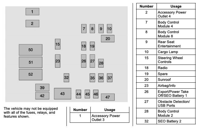
Key Specs and Main Parts
The 2014 Silverado 1500 typically has two main fuse box locations:
- Underhood Fuse Box: Located in the engine compartment, this box houses high-amperage fuses and relays that control critical systems like the engine, transmission, brakes (ABS), and headlights.
- Interior Fuse Box: Typically located under the dashboard on the driver's side (sometimes behind a small panel), this box manages lower-amperage circuits for interior components like power windows, door locks, radio, and interior lights.
The specific fuses and relays present in each box will vary depending on the truck's options and trim level (e.g., 2WD vs. 4WD, LT vs. LTZ). The diagram will indicate:
- Fuse Number: A unique identifier for each fuse (e.g., F1, F2, F3...).
- Circuit Description: A brief explanation of what the fuse protects (e.g., "Headlight - Left," "Radio," "Power Window - Driver").
- Amperage Rating: The maximum current the fuse can handle before blowing (e.g., 10A, 15A, 20A...). This is usually indicated by a number on the fuse itself and color-coded (more on that later).
- Fuse Type: Indicates the physical style of the fuse (e.g., ATO, Mini ATO, Micro2). These have different sizes and connector styles, so knowing the type is important for replacement.
- Relay Location and Function: (In the underhood fuse box) Relays are electromechanical switches that control high-current circuits. The diagram will show their position and which circuits they switch (e.g., "Starter Relay," "Fuel Pump Relay").
Understanding the Symbols
Fuse box diagrams aren't just lists of numbers and words; they often use symbols and conventions to convey information efficiently. Here's what to look for:
- Lines: Solid lines typically represent wiring connections. Dashed lines might indicate alternative wiring paths or connections that are not always present.
- Colors: Wire colors are often noted on the diagram (e.g., RED, BLU, GRN). This helps you trace wires in the actual harness. Be aware that wire colors can fade or change over time due to heat and environmental factors, so use caution.
- Fuse Symbols: A standard fuse symbol (often a wavy line inside a rectangle) clearly marks the location of each fuse.
- Relay Symbols: Relays are usually represented by a square with a diagonal line or a more complex symbol showing the coil and switch contacts.
- Ground Symbols: A ground symbol (often three lines decreasing in size) indicates the point where a circuit connects to the vehicle's chassis for a common ground.
- Connector Symbols: Connectors (where wires plug into modules or other wiring harnesses) are usually shown as circles or rectangles with numbers indicating pin assignments.
- Abbreviations: Expect to see abbreviations for common components and circuits (e.g., ECM - Engine Control Module, BCM - Body Control Module, A/C - Air Conditioning). A legend is often provided on the diagram to explain these.
How It Works: Following the Circuit
The beauty of a fuse box diagram is that it allows you to trace a circuit from the power source (battery) through the fuse, switch, relay (if any), and finally to the load (the component being powered). Consider this simplified example:
Suppose your diagram shows that Fuse F20 (15A) in the interior fuse box protects the driver's side power window. If the power window is not working, you can:
- Check the fuse: Visually inspect Fuse F20. If it's blown (the internal filament is broken), replace it with a new 15A fuse. Never use a higher amperage fuse; this can damage the wiring and component.
- If the fuse blows again immediately: There's a short circuit in the power window circuit downstream from the fuse. This could be in the wiring, the power window motor, or the switch. The diagram can help you identify the wiring path to check for shorts (e.g., a pinched wire).
- If the fuse is good but the window still doesn't work: The problem is likely not the fuse itself. You'll need to investigate the power window switch, wiring connections, and the motor itself, using the wiring diagram in conjunction with the fuse box diagram. A multimeter will be essential for testing voltage and continuity.
Real-World Use: Basic Troubleshooting Tips
Here are some practical tips for using your 2014 Silverado 1500 fuse box diagram for troubleshooting:
- Start with the basics: Always check the fuse first. It's the easiest and cheapest potential fix.
- Use a test light or multimeter: A test light can quickly check if power is reaching a fuse. A multimeter can measure voltage, current, and resistance for more in-depth diagnostics.
- Consult the owner's manual: Your owner's manual may contain a simplified fuse box diagram and descriptions.
- Look for common problems: Certain circuits are prone to issues (e.g., trailer wiring, aftermarket accessories).
- Don't assume: Just because one component isn't working doesn't mean the fuse is the problem. Systematically check each component in the circuit.
- Document your work: Keep a record of what you've checked and the results. This can help you track down intermittent problems.
Safety Considerations
Working with automotive electrical systems can be dangerous. Keep these safety tips in mind:
- Disconnect the battery: Whenever possible, disconnect the negative battery terminal before working on any electrical circuit. This prevents accidental shorts.
- Avoid working on live circuits: If you must work on a live circuit, use extreme caution and wear appropriate safety glasses and gloves.
- Don't overload circuits: Never install a fuse with a higher amperage rating than specified in the diagram.
- Be aware of airbags: Airbag circuits are highly sensitive. Avoid disturbing wiring near airbags unless you know what you're doing. Improper handling can cause accidental deployment.
- High Current components The high current components inside the underhood fuse box (relays and fuses for the starter, alternator, etc.) can deliver a significant electrical shock. Exercise extreme caution when working in this area, and always disconnect the battery when possible.
- Consult a professional: If you're not comfortable working on electrical systems, consult a qualified mechanic.
Having a 2014 Chevy Silverado 1500 fuse box diagram at your fingertips is crucial for maintaining and repairing your truck. By understanding the layout, symbols, and functions of the fuses and relays, you can confidently tackle a wide range of electrical tasks.
We have the full 2014 Chevy Silverado 1500 fuse box diagram readily available for download. It contains detailed information on both the underhood and interior fuse box locations, complete with fuse numbers, circuit descriptions, and amperage ratings. You can download it here.