2014 Chevy Silverado Drivers Door Wiring Harness
Alright, let's dive into the 2014 Chevy Silverado driver's door wiring harness. Understanding this system is crucial for everything from basic repairs to advanced modifications. This article will serve as your guide to understanding the intricacies of this critical component.
Why Understand the Driver's Door Wiring Harness?
The driver's door wiring harness is more than just a collection of wires. It's the central nervous system connecting your driver's door components (power windows, door locks, mirrors, speakers, etc.) to the rest of your Silverado's electrical system. Access to and understanding of the wiring diagram becomes invaluable when:
- Troubleshooting electrical problems: Diagnosing why your power window won't roll down, why your door locks aren't responding, or why your side mirror is dead.
- Performing repairs: Replacing damaged wires, connectors, or even the entire harness.
- Installing aftermarket accessories: Adding new speakers, security systems, or custom lighting features.
- General learning: Gaining a deeper understanding of your vehicle's electrical architecture.
Key Specs and Main Parts of the 2014 Silverado Driver's Door Harness
The 2014 Silverado driver's door wiring harness is a complex assembly, and its exact configuration can vary slightly depending on the trim level (e.g., WT, LS, LT, LTZ, High Country) and options (e.g., power folding mirrors, heated mirrors, memory seats). However, some common components and specs include:
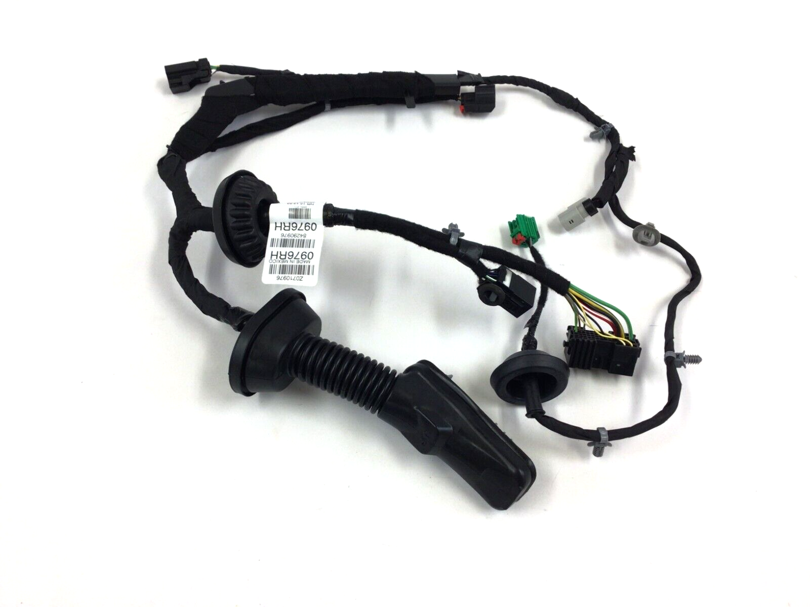
Main Parts:
- The Main Harness: The primary bundle of wires that connects to the vehicle's body and branches out to individual door components.
- Connectors: Various types of connectors (weatherpack, Metri-Pack) are used to interface with door modules, switches, motors, and other devices. These ensure secure and reliable electrical connections.
- Ground Wires: Typically black and often connected to a grounding point within the door frame to provide a return path for electrical current.
- Power Wires: Usually thicker gauge wires to handle the higher current demands of components like power windows and door locks. They are often red or orange.
- Signal Wires: Smaller gauge wires used for transmitting signals from switches and sensors to control modules.
- Splice Packs: Locations where multiple wires are joined together. These are typically covered with protective tape or heat shrink tubing.
Key Specifications:
- Wire Gauge: Wire gauge (AWG - American Wire Gauge) indicates the wire's thickness and current-carrying capacity. Common gauges in the door harness include 18 AWG, 16 AWG, 14 AWG, and 12 AWG. Larger numbers indicate thinner wires.
- Wire Insulation: Wires are insulated with different types of materials (PVC, XLPE) to protect them from abrasion, heat, and chemicals.
- Connector Types: Specific connector series (e.g., Metri-Pack 150, Weatherpack) are chosen based on their current rating, environmental sealing, and locking mechanisms.
- Voltage: Most circuits in the door harness operate at the vehicle's nominal voltage of 12V DC.
Understanding Wiring Diagram Symbols, Lines, and Colors
A wiring diagram is a symbolic representation of the electrical circuit. Understanding these symbols is vital to making sense of the harness. Here's a breakdown of common elements:
- Lines: Solid lines represent wires. Dashed lines often indicate shielded wires or connections within a module.
- Colors: Each wire is color-coded for identification. Common colors include:
- BK: Black (Ground)
- RD: Red (Power)
- OR: Orange (Power)
- WH: White
- GN: Green
- BL: Blue
- TN: Tan
- GY: Gray
- PK: Pink
- VT: Violet (Purple)
- Combinations (e.g., WH/BK) indicate a white wire with a black stripe.
- Components: Symbols represent various electrical components. Some common symbols include:
- Resistors: A zigzag line.
- Capacitors: Two parallel lines.
- Switches: A line with a break, showing how the circuit is opened or closed. Various switch types are depicted with different configurations.
- Relays: A coil with a switch contact.
- Motors: A circle with an "M" inside.
- Fuses: A wavy line inside a rectangle.
- Grounds: A downward-pointing triangle or a series of decreasing parallel lines.
- Connectors: Circles or rectangles representing the connector body, with lines indicating the pins and wire connections.
- Numbers and Letters: Each wire is typically labeled with a circuit number and a letter code indicating its function or destination.
Understanding the color codes is vital for tracing wires throughout the harness. Without this knowledge, it's easy to misidentify circuits, potentially causing more damage.
How the Driver's Door Wiring Harness Works
The driver's door wiring harness acts as a conduit, carrying electrical signals and power to and from various components within the door. The Body Control Module (BCM) is often the central control unit that manages many of these functions.
For example, when you press the power window switch, the switch sends a signal to the BCM. The BCM then energizes a relay, which sends power to the window motor, causing it to move the window up or down. Similarly, when you press the door lock switch, the switch sends a signal to the BCM, which then activates the door lock actuators.
The wiring harness also carries signals from sensors, such as the door ajar sensor, to the BCM. The BCM uses this information to determine whether the door is open or closed, and it may activate the dome light or sound a warning chime.
Real-World Use: Basic Troubleshooting Tips
Here are some basic troubleshooting steps you can take using the wiring diagram:
- Identify the Problem: Pinpoint which component isn't working (e.g., power window, door lock, speaker).
- Consult the Wiring Diagram: Locate the circuit diagram for the problematic component. Identify the wires, connectors, and related components in the circuit.
- Check Fuses and Relays: Verify that the fuse protecting the circuit is not blown and that the relay is functioning correctly. A multimeter can be used to test continuity and voltage.
- Inspect Connectors: Examine the connectors for corrosion, loose connections, or damage. Clean or replace connectors as needed.
- Trace Wires: Use a multimeter to check for continuity (a complete circuit) and voltage along the wire. Look for breaks, shorts, or damage to the wire insulation.
- Test the Component: If possible, test the component directly to rule out a faulty component. For example, you can apply power directly to the window motor to see if it operates.
Example: Let's say your power window isn't working. First, check the fuse for the power window circuit. If the fuse is good, consult the wiring diagram to locate the power window motor, the switch, and the relevant wiring. Use a multimeter to check for voltage at the motor connector when the switch is activated. If there's no voltage, trace the wiring back towards the switch, checking for breaks or shorts along the way. A systematic approach, guided by the wiring diagram, will greatly increase your chances of finding the problem.
Safety Considerations
Working with electrical systems can be dangerous. Here are some critical safety precautions:
- Disconnect the Battery: Always disconnect the negative battery cable before working on the electrical system to prevent accidental shorts or shocks.
- Use Proper Tools: Use insulated tools to avoid electrical shocks.
- Be Careful with Airbags: The side impact airbags are located in the door. Handle airbag wiring with extreme caution. Disconnect the battery and wait at least 10 minutes before working near airbag components to allow the system to discharge. Incorrect handling can cause accidental deployment.
- Avoid Working in Wet Conditions: Never work on electrical systems in wet or damp conditions.
- Never probe connectors with sharp objects. This can damage the connector and cause future problems. Use specialized test leads designed for this purpose.
High-Risk Components: The airbag wiring and the power window motor circuit carry significant electrical energy. Exercise extreme caution when working with these circuits.
By understanding the 2014 Chevy Silverado driver's door wiring harness, you'll be better equipped to diagnose, repair, and modify your vehicle's electrical system. Remember to always prioritize safety and consult the wiring diagram before attempting any repairs or modifications. We have access to the complete wiring diagram file, which you can download for a more detailed view of the system and for reference during troubleshooting.