2014 Chrysler Town And Country Fuse Box Diagram
Let's dive into the 2014 Chrysler Town & Country fuse box diagram. This isn't just a pretty picture; it's your roadmap to electrical troubleshooting and modifications. Whether you're diagnosing a faulty turn signal, upgrading your sound system, or just curious about your minivan's inner workings, understanding the fuse box is crucial. This guide will provide you with the technical understanding needed to safely and effectively work with your vehicle’s electrical system.
Purpose of the Fuse Box Diagram
Why bother with a fuse box diagram? Simple: it's essential for:
- Electrical Repairs: Identifying the correct fuse or relay for a specific circuit. A blown fuse is often the first suspect in an electrical problem.
- Modifications & Upgrades: Safely tapping into existing circuits for accessories like aftermarket lighting or a dashcam. You need to know what circuit you are tapping into to avoid overloading it.
- Learning Your Vehicle: Gaining a deeper understanding of how your Town & Country's electrical system is organized. This makes diagnosing issues and performing maintenance much easier.
- Preventing Further Damage: Replacing a blown fuse with the correct amperage rating prevents damage to the electrical components it protects. Using the wrong fuse can lead to a fire or further damage.
Think of the fuse box diagram as the electrical system's index. It tells you what each fuse and relay controls, its amperage rating, and its physical location within the fuse box(es).
Key Specs and Main Parts
The 2014 Town & Country actually has two main fuse boxes:
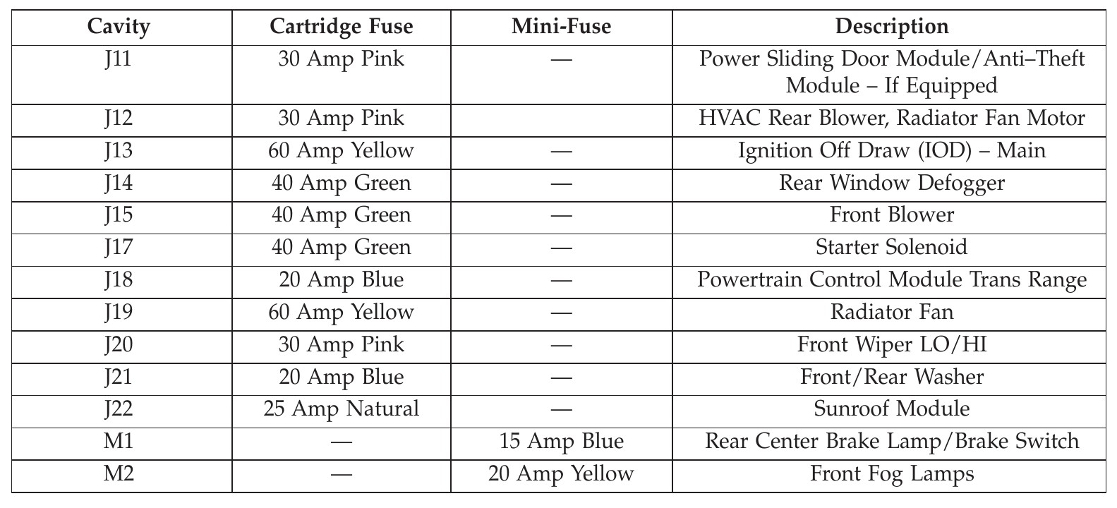
- Underhood Fuse Box (Power Distribution Center - PDC): Located in the engine compartment, this box houses fuses and relays for high-current components like the starter, alternator, cooling fan, headlights, and various other engine and chassis control systems.
- Interior Fuse Box (Central Junction Box - CJB): Situated inside the cabin, often behind a panel in the glove compartment or driver's side footwell, this box handles circuits for interior accessories like the radio, power windows, power locks, and interior lighting.
Key Specs to Note:
- Fuse Amperage Ratings: Expressed in Amperes (A). Common ratings include 5A, 10A, 15A, 20A, 25A, 30A, and 40A. Always replace a blown fuse with one of the *same* amperage rating.
- Fuse Types: The 2014 Town & Country uses blade-type fuses, specifically ATO (Automotive Transportation Organization) and Mini fuses. These are easily identifiable by their plastic bodies and exposed metal terminals.
- Relays: Electromagnetic switches that control high-current circuits with a low-current signal. They are typically larger than fuses and often plug into sockets in the fuse box.
Understanding Fuse Box Symbols
The fuse box diagram uses a standardized set of symbols to represent different components and circuit characteristics. While the specific symbology might vary slightly between diagrams, here are the basics:
- Fuses: Typically represented by a zigzag line enclosed in a rectangle or a simple rectangle with a number indicating the amperage rating.
- Relays: Often shown as a rectangle with a coil symbol inside, representing the relay's electromagnet. Connections to the coil and the switch are also indicated.
- Lines: Represent wires connecting the components. Line thickness doesn't necessarily indicate wire gauge.
- Colors: Diagrams may use color-coding to distinguish between different circuits or wire functions (e.g., red for power, black for ground). However, relying solely on wire color for identification can be risky, as colors can fade or vary depending on aftermarket modifications. Always verify with a multimeter.
- Icons: Specific icons may represent the component powered by the fuse (e.g., a headlight icon for the headlight fuse, a radio icon for the radio fuse).
- Ground Symbols: A series of decreasing lines or a triangle pointing downwards, indicating a connection to the vehicle's chassis ground.
Pay close attention to the legend or key provided with the diagram. This will explain the specific symbols and conventions used in that particular diagram.
How It Works: Basic Circuit Theory
Understanding the basics of how a circuit functions is essential for troubleshooting. Here's a simplified explanation:
A circuit is a closed loop that allows electrical current to flow from a power source (the battery) through a load (a device that consumes electricity, like a light bulb) and back to the power source. The fuse is a safety device placed in the circuit to protect it from overcurrent. When the current exceeds the fuse's rating, the fuse's internal element melts, breaking the circuit and stopping the flow of current.
Ohm's Law (V=IR) is a fundamental principle: Voltage (V) equals Current (I) times Resistance (R). Overcurrent can occur due to a short circuit (low resistance) or excessive load (too many devices drawing current). The fuse protects the wiring and components from the damaging effects of overcurrent, such as overheating and fire.
The relay, as mentioned, acts as a switch. A small current flows through the relay's coil, creating an electromagnetic field that pulls the switch closed, allowing a larger current to flow through the circuit it controls. This allows a low-current signal from a switch or control module to control a high-current device like a starter motor or a high-powered fan.
Real-World Use: Basic Troubleshooting Tips
Here's how to use the fuse box diagram for troubleshooting:
- Identify the Problem: Determine which component is malfunctioning (e.g., the windshield wipers don't work).
- Consult the Diagram: Locate the fuse and/or relay associated with that component in the appropriate fuse box diagram (underhood or interior).
- Inspect the Fuse: Visually inspect the fuse. If the element inside is broken, the fuse is blown. You can also use a multimeter set to continuity mode to test the fuse. A working fuse will show continuity (a beep or a reading close to zero ohms).
- Replace the Fuse (if blown): Replace the blown fuse with a new fuse of the *same* amperage rating. Do NOT use a higher amperage fuse.
- Test the Circuit: After replacing the fuse, test the component to see if it now works.
- If the Fuse Blows Again: If the new fuse blows immediately or shortly after being replaced, there is a short circuit or excessive load in the circuit. Further diagnosis is required, and you may need to consult a professional mechanic.
Common causes of blown fuses include:
- Short Circuits: Worn or damaged wiring can cause a short circuit, where the current bypasses the intended load and flows directly to ground.
- Overloaded Circuits: Adding too many accessories to a single circuit can overload it, causing the fuse to blow.
- Faulty Components: A malfunctioning component can draw excessive current, causing the fuse to blow.
Safety Considerations
Working with electrical systems can be dangerous. Here are some crucial safety precautions:
- Disconnect the Battery: Before working on any electrical components, disconnect the negative (-) terminal of the battery. This prevents accidental shorts and electrical shocks.
- Use the Right Tools: Use insulated tools designed for automotive electrical work.
- Never Bypass a Fuse: Never replace a fuse with a wire or a higher amperage fuse. This can cause a fire or serious damage to the electrical system.
- Be Careful with High-Voltage Components: Some components, such as the ignition system and the airbag system, operate at high voltage. These components should only be serviced by qualified technicians. Especially avoid the airbag system. Mishandling it can lead to serious injury.
- Wear Safety Glasses: Protect your eyes from sparks or debris.
The Power Distribution Center (PDC) under the hood handles higher current and voltage components. Exercise extra caution when working in this area.
Remember, if you're not comfortable working with electrical systems, it's always best to consult a qualified mechanic. Electrical problems can be complex and diagnosing them requires specialized knowledge and equipment.
We have the 2014 Chrysler Town & Country Fuse Box Diagram available for you to download. Refer to it often as you maintain and modify your vehicle. Safe wrenching!