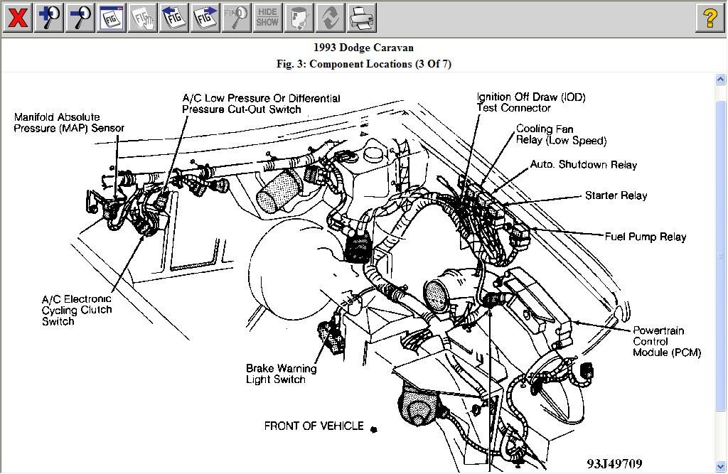
2014 Chrysler Town And Country Parts Diagram
Alright, let's dive into the 2014 Chrysler Town & Country parts diagram. This isn't just some pretty picture; it's your roadmap for understanding, maintaining, and repairing your minivan. Think of it as the Rosetta Stone for your vehicle's inner workings. Whether you’re tackling a routine maintenance task, diagnosing a mysterious clunk, or planning a modification, knowing how to read and interpret this diagram is crucial.
Purpose: Your Repair and Understanding Companion
Why bother with a parts diagram? Simple: it empowers you. It allows you to:
- Identify parts accurately: No more guessing games at the auto parts store. You'll know exactly what you need.
- Understand assembly: See how components fit together, making disassembly and reassembly far less daunting.
- Troubleshoot problems: The diagram can point you to potential problem areas based on the affected systems.
- Plan repairs: Knowing the location and relationship of parts helps you estimate repair time and complexity.
- Order parts online: Accurate part numbers are your key to getting the right components from online retailers.
Key Specs and Main Parts
The 2014 Town & Country, like most vehicles, has a multitude of parts diagrams covering different systems. However, let's focus on some of the most commonly referenced systems and the information found within their diagrams:
Engine Components:
The engine diagram will detail everything from the 3.6L Pentastar V6 engine block to the individual components like:
- Cylinder Head: Includes valves, springs, retainers, and camshaft.
- Pistons and Connecting Rods: Shows the internal reciprocating assembly.
- Crankshaft: The heart of the engine's rotation.
- Intake Manifold: Directs air into the cylinders.
- Exhaust Manifold: Collects exhaust gases from the cylinders.
- Timing Chain/Belt: Synchronizes the crankshaft and camshaft.
- Water Pump: Circulates coolant to regulate engine temperature.
Transmission Components:
The 62TE six-speed automatic transmission is commonly used. Diagrams will illustrate:
- Torque Converter: Transfers engine power to the transmission.
- Valve Body: Controls hydraulic pressure for gear shifting.
- Gears and Shafts: Shows the internal gear ratios and their arrangement.
- Transmission Case: The housing for all internal components.
- Differential: Allows the wheels to rotate at different speeds.
Suspension and Steering:
Details the front and rear suspension systems, including:
- Struts/Shocks: Damping devices that control suspension movement.
- Control Arms: Connect the wheels to the vehicle's frame.
- Ball Joints: Allow for steering and suspension movement.
- Tie Rods: Connect the steering rack to the steering knuckles.
- Steering Rack/Gearbox: Converts steering wheel input into linear motion.
Braking System:
Including both hydraulic and mechanical components:
- Brake Master Cylinder: Supplies hydraulic pressure to the brake calipers/wheel cylinders.
- Brake Calipers: Squeeze the brake pads against the rotors.
- Brake Rotors/Drums: Provide a friction surface for the brake pads/shoes.
- Brake Lines: Carry hydraulic fluid to the brakes.
- ABS Module: Controls the Anti-lock Braking System.
Electrical System:
From wiring harnesses to control modules:
- Wiring Harnesses: Bundles of wires that connect electrical components.
- Fuses and Relays: Protect electrical circuits from overload.
- ECU (Engine Control Unit): The "brain" of the engine.
- BCM (Body Control Module): Controls various body functions.
- Sensors: Provide data to the control modules (e.g., oxygen sensor, temperature sensor).
Symbols: Deciphering the Diagram
Understanding the symbols used in the diagram is essential. Here's a breakdown:
- Solid Lines: Typically represent rigid connections, like pipes, tubes, or solid mechanical linkages.
- Dashed Lines: Usually indicate flexible connections, like hoses or wiring harnesses.
- Dotted Lines: Often represent vacuum lines or hidden components.
- Arrows: Indicate the direction of flow (e.g., fluid flow in a hydraulic system).
- Circles: Can represent various components, depending on the context (e.g., gears, seals, fittings).
- Squares/Rectangles: Commonly used to represent electrical components, like relays, switches, or control modules.
- Part Numbers: Each component is typically labeled with a unique part number. This is crucial for ordering replacements.
- Fastener Torque Specs: Some diagrams also include torque specifications for bolts and nuts, which are essential for proper reassembly.
Color coding, if present, can further clarify the diagram. For instance, different colors might represent different fluids (e.g., red for transmission fluid, green for coolant) or different voltage levels in the electrical system.
How It Works: Putting the Pieces Together
The diagram illustrates the relationships between parts. It's not just a collection of individual components; it shows how they interact to perform a specific function. For example, the engine diagram reveals how the intake manifold directs air into the cylinders, where it mixes with fuel and is ignited to create power. The transmission diagram shows how different gears engage to change the vehicle's speed and torque. Understanding these relationships is key to troubleshooting problems effectively.
Many diagrams use an exploded view, showing how the components are assembled in a step-by-step manner. This is particularly helpful when disassembling and reassembling complex components, like the transmission or engine.
Real-World Use: Basic Troubleshooting Tips
Let's say you're experiencing a coolant leak. By consulting the cooling system diagram, you can trace the coolant lines, identify potential leak points (e.g., hoses, connections, water pump), and pinpoint the source of the leak. Or, if you notice a misfire, you can use the engine diagram to check the spark plugs, ignition coils, and fuel injectors. The diagram can also help you identify the location of sensors that might be causing the misfire.
Here's a basic troubleshooting workflow using the parts diagram:
- Identify the problem: Describe the symptoms as accurately as possible.
- Consult the relevant diagram: Locate the diagram for the system you suspect is causing the problem.
- Trace the system: Follow the lines and components in the diagram to understand how the system works.
- Identify potential problem areas: Look for components that are known to fail or that are located in areas that are prone to damage.
- Inspect the components: Physically inspect the components for signs of damage, wear, or leaks.
- Test the components: Use a multimeter or other testing equipment to check the functionality of the components.
Safety: Handle with Care
Working on your vehicle can be dangerous if you're not careful. Here are some safety precautions to keep in mind:
- Disconnect the battery: Before working on any electrical components, disconnect the negative battery cable to prevent electrical shock.
- Relieve pressure: Before disconnecting any hydraulic lines (e.g., brake lines, power steering lines), relieve the pressure in the system to prevent fluid spills.
- Support the vehicle: When working under the vehicle, use jack stands to support it securely. Never rely on a jack alone.
- Wear safety glasses: Protect your eyes from flying debris.
- Work in a well-ventilated area: Avoid breathing in fumes from gasoline, oil, or other chemicals.
- High-Voltage Components: Be extremely cautious when working near the ignition system. The ignition coils can generate extremely high voltages. Even when the engine is off, residual voltage can remain in the system.
- Fuel System: The fuel system is under pressure. When disconnecting fuel lines, be prepared for fuel to spray out. Work in a well-ventilated area and avoid sparks or open flames.
Remember, some repairs are best left to qualified mechanics. If you're not comfortable with a particular task, don't hesitate to seek professional help.
This overview should give you a solid foundation for understanding and using the 2014 Chrysler Town & Country parts diagram. With a little practice, you'll be able to navigate the diagrams with confidence and tackle a wide range of repairs and maintenance tasks.
We have the full parts diagram file available for download. It contains detailed illustrations and part numbers for all major systems of your 2014 Chrysler Town & Country. Happy wrenching!