
2014 Ford Escape Coolant System Diagram
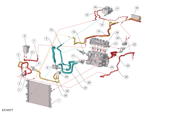
For the experienced DIY mechanic or car enthusiast tackling cooling system maintenance on a 2014 Ford Escape, a detailed coolant system diagram is an indispensable tool. Whether you're flushing the system, diagnosing a leak, or replacing a component, understanding the layout and function of each part will save you time, money, and potential headaches. This article breaks down the 2014 Ford Escape coolant system diagram, explaining its key components, symbols, and troubleshooting tips. We'll also cover important safety considerations to ensure you work safely.
Purpose of a Coolant System Diagram
A coolant system diagram, sometimes called a cooling system schematic, serves several crucial purposes:
- Diagnosis: It helps pinpoint the location of leaks, blockages, or malfunctioning components. Visualizing the coolant flow path makes tracing problems significantly easier.
- Repair and Maintenance: The diagram guides you through the proper disassembly and reassembly of the system, ensuring you don't miss any steps or connections. It's especially valuable when replacing hoses, the water pump, or the thermostat.
- Understanding System Operation: Beyond repairs, the diagram provides a comprehensive understanding of how the coolant system works to regulate engine temperature. This knowledge is invaluable for preventative maintenance and recognizing potential issues before they become major problems.
- Modifications: For those considering modifications, such as adding an auxiliary cooler or upgrading components, the diagram is essential for planning and executing changes correctly.
Key Specs and Main Parts (2014 Ford Escape)
The 2014 Ford Escape cooling system varies slightly depending on the engine (1.6L EcoBoost, 2.0L EcoBoost, or 2.5L Duratec), but the fundamental components and principles remain the same. Here's an overview:
Main Components:
- Radiator: The primary heat exchanger. Hot coolant from the engine passes through the radiator's core, where air flowing through the fins dissipates heat.
- Water Pump: A mechanical pump driven by the engine's accessory belt (or timing chain in some designs). It circulates the coolant throughout the system.
- Thermostat: A temperature-sensitive valve that regulates coolant flow to the radiator. It remains closed when the engine is cold, allowing it to warm up quickly. Once the engine reaches operating temperature, the thermostat opens, allowing coolant to flow to the radiator.
- Coolant Reservoir (Expansion Tank): A plastic container that holds excess coolant. It allows for expansion and contraction of the coolant as its temperature changes. It also allows you to visually check the coolant level.
- Hoses: Various hoses connect the different components of the cooling system. These hoses are typically made of rubber or silicone and are designed to withstand high temperatures and pressures.
- Heater Core: A small radiator located inside the vehicle's cabin. Hot coolant flows through the heater core, and a fan blows air across it to provide heat to the cabin.
- Radiator Cap: Maintains system pressure (typically around 16 PSI). This pressure raises the boiling point of the coolant, preventing it from boiling over at high engine temperatures. It also incorporates a pressure relief valve to vent excess pressure.
- Cooling Fan(s): Electric fans mounted behind the radiator that draw air through the radiator when the vehicle is stationary or moving slowly. They are controlled by the engine control unit (ECU) based on coolant temperature.
Coolant Type:
The 2014 Ford Escape typically uses a Motorcraft Orange coolant meeting Ford specification WSS-M97B44-D. Always verify the correct coolant specification in your vehicle's owner's manual or on the coolant reservoir cap. Using the wrong coolant can lead to corrosion and damage to the system.
Understanding Coolant System Diagram Symbols
Coolant system diagrams use a standardized set of symbols to represent different components and flow paths. Here's a breakdown of common symbols:
- Solid Lines: Generally represent the main coolant flow paths. The thickness of the line might indicate the hose diameter or flow rate.
- Dashed Lines: Often represent vacuum lines, signal lines, or control lines related to the cooling system (e.g., signals to the cooling fan relay).
- Arrows: Indicate the direction of coolant flow.
- Radiator Symbol: Usually a rectangular shape with fins or zig-zag lines inside to represent the core.
- Water Pump Symbol: Often a circular shape with an impeller symbol inside.
- Thermostat Symbol: A valve symbol, often with a coil to indicate temperature sensitivity.
- Heater Core Symbol: Similar to the radiator symbol, but smaller and often located inside the passenger compartment.
- Temperature Sensor Symbol: A circle with a "T" inside or a similar symbol indicating a temperature-sensing device.
Color coding, if present, can also provide valuable information. For example:
- Red: Often indicates hot coolant flow.
- Blue: Often indicates cooler coolant flow.
Consult the specific diagram legend for a complete explanation of all symbols used.
How the Coolant System Works
The cooling system's primary function is to maintain the engine at its optimal operating temperature. Here's a simplified explanation of the process:
- The water pump circulates coolant through the engine block and cylinder head(s).
- As the coolant passes through the engine, it absorbs heat generated by combustion.
- The hot coolant then flows towards the thermostat.
- If the engine is cold (below the thermostat's opening temperature), the thermostat remains closed, and the coolant is redirected back to the water pump for recirculation within the engine, allowing it to warm up quickly.
- Once the engine reaches operating temperature, the thermostat opens, allowing the hot coolant to flow to the radiator.
- In the radiator, the coolant releases heat to the surrounding air.
- The cooled coolant then returns to the water pump to repeat the cycle.
- The cooling fan(s) assist in dissipating heat from the radiator, especially when the vehicle is stationary or moving slowly.
- The heater core provides heat to the vehicle's interior by diverting some of the hot coolant through a small radiator inside the cabin.
- The coolant reservoir accommodates the expansion and contraction of the coolant as its temperature changes, preventing pressure buildup in the system.
Real-World Use and Basic Troubleshooting
Here are some common coolant system issues and how the diagram can help with troubleshooting:
- Overheating: The diagram helps you trace the coolant flow to identify potential blockages in hoses, the radiator, or the thermostat. Check for proper operation of the cooling fan(s) by verifying power and ground to the fan motor and relay.
- Coolant Leaks: Use the diagram to identify potential leak sources, such as hoses, the water pump, the radiator, or the thermostat housing. Inspect these areas closely for signs of coolant residue. A pressure tester can help pinpoint difficult-to-find leaks.
- No Heat: Check the heater core hoses for proper coolant flow. A blockage in the heater core or a malfunctioning heater control valve (if equipped) can prevent heat from reaching the cabin.
- Low Coolant Level: Regularly check the coolant level in the reservoir. Frequent topping off indicates a leak somewhere in the system.
Safety Considerations
Working on the cooling system can be dangerous if proper precautions are not taken. Here are some important safety tips:
- Never open the radiator cap or coolant reservoir cap when the engine is hot. The system is under pressure, and hot coolant can spray out, causing severe burns. Wait until the engine has cooled down completely before opening the cap.
- Be careful when working around the electric cooling fans. They can turn on unexpectedly, even when the engine is off. Disconnect the negative battery cable to prevent accidental activation.
- Wear safety glasses and gloves to protect your eyes and skin from coolant. Coolant is toxic and can cause irritation.
- Dispose of used coolant properly. Do not pour it down the drain or onto the ground. Take it to a recycling center or auto parts store that accepts used coolant.
- Be aware that some components, like the radiator and certain hoses, can remain hot for a considerable time after the engine is shut off. Exercise caution when working around these areas.
- The water pump, driven by the serpentine belt, is another area requiring careful attention. Ensure the engine is off and the key is removed to prevent accidental belt movement during inspection or replacement.
Working on a pressurized system like the cooling system requires caution. Always relieve pressure before opening any components.
With a 2014 Ford Escape coolant system diagram and the knowledge gained from this article, you'll be well-equipped to tackle cooling system maintenance and repairs with confidence. Remember to always prioritize safety and consult the specific service manual for your vehicle for detailed instructions and torque specifications.
We have the detailed 2014 Ford Escape Coolant System Diagram file available for download. This will be a valuable resource for your repair and maintenance needs.