2014 Ford Escape Rear Suspension Diagram
Let's dive into the rear suspension of a 2014 Ford Escape. Understanding this system is crucial for anyone looking to perform maintenance, repairs, modifications, or even just deepen their general automotive knowledge. This article will serve as a comprehensive guide, walking you through the 2014 Ford Escape rear suspension diagram, its components, and functionality. We'll cover the key parts, their roles, and some common troubleshooting tips. And remember, we have the complete diagram file available for download (link provided at the end), giving you a valuable reference during your work.
Purpose of Understanding the Rear Suspension Diagram
Why bother with a diagram? Well, the rear suspension is a complex system. The diagram acts as a roadmap. It allows you to:
- Accurately identify parts: Knowing the correct name and location of each component is essential for ordering replacements or discussing repairs with a professional.
- Understand the system's operation: Seeing how everything connects helps you grasp how the suspension works to provide a comfortable ride and stable handling.
- Troubleshoot problems efficiently: A diagram helps you visualize the potential causes of issues like unusual noises, uneven tire wear, or poor handling.
- Perform repairs and modifications safely: With a clear understanding of the layout, you can tackle tasks like replacing shocks, springs, or control arms with confidence.
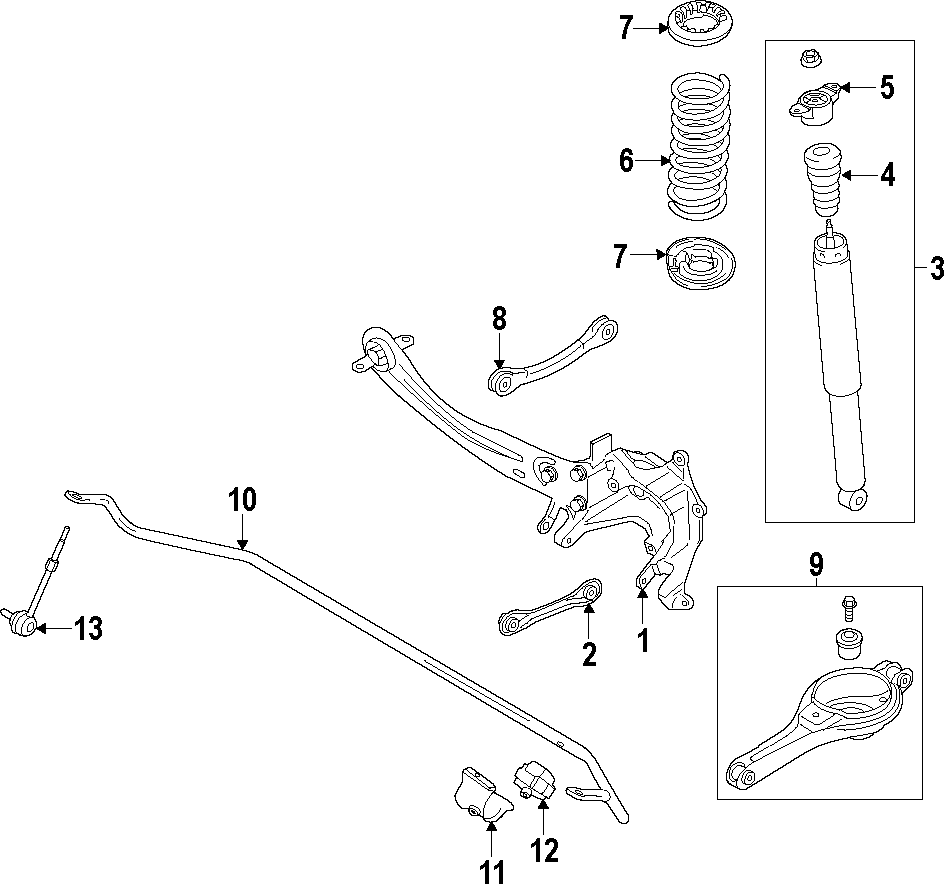
Key Specs and Main Parts of the 2014 Ford Escape Rear Suspension
The 2014 Ford Escape uses an independent multi-link rear suspension. This design offers a good balance between ride comfort and handling performance. Let's break down the main components:
Major Components:
- Shocks (or Dampers): These control the movement of the suspension by damping oscillations. They convert kinetic energy into heat, preventing the vehicle from bouncing excessively. Look for part numbers and mounting orientations in the diagram.
- Coil Springs: These support the vehicle's weight and absorb bumps in the road. The diagram shows the spring's location relative to the shock and control arms.
- Lower Control Arms: These connect the wheel hub to the vehicle's frame. They control the wheel's vertical movement and contribute to stability. The diagram illustrates their pivot points and bushing locations.
- Upper Control Arms (or Lateral Links): These provide additional stability and control the wheel's camber (the angle of the wheel relative to vertical). The diagram highlights their mounting points and adjustability (if any).
- Toe Link (or Track Control Arm): This link controls the wheel's toe angle (the angle of the wheel relative to the vehicle's centerline). It's often adjustable for alignment purposes.
- Stabilizer Bar (or Anti-Roll Bar): This bar connects the left and right sides of the suspension to reduce body roll during cornering. The diagram shows its mounting brackets and end links.
- Wheel Hub/Bearing Assembly: This assembly houses the wheel bearing, which allows the wheel to rotate smoothly. It's bolted to the suspension components.
- Knuckle (or Spindle): This component connects the wheel hub/bearing assembly to the control arms.
- Bushings: These are rubber or polyurethane insulators that cushion the connection points between suspension components. They absorb vibrations and reduce noise. The diagram shows the location of all bushings within the suspension system.
Key Specs to Note:
While the diagram primarily shows component layout, it's often associated with technical service information containing critical specs. Be on the lookout for:
- Torque Specifications: The diagram can guide you to torque specs for all bolts and fasteners, ensuring proper tightening and preventing damage.
- Alignment Specifications: Values for camber, caster, and toe are crucial for proper handling and tire wear. The diagram helps you identify the adjustment points for these parameters.
- Spring Rates: Knowing the spring rate helps when replacing or upgrading springs.
Understanding Symbols in the Diagram
Suspension diagrams use a standardized set of symbols to represent different components and connections. Here's a breakdown of common symbols:
- Solid Lines: Typically represent rigid components like control arms, springs, and the stabilizer bar.
- Dashed Lines: Often indicate hidden components or lines running behind other parts.
- Arrows: Show the direction of movement or force. For example, arrows near the shocks might indicate the direction of damping force.
- Circles/Dots: Usually represent fasteners like bolts, nuts, and rivets. Their size might indicate the fastener's diameter.
- Hatching: Can indicate a cross-sectional view of a component, revealing its internal structure.
- Colors: While not always present, colors can be used to differentiate between different types of components or systems. For instance, one color might represent the brake lines, while another represents the suspension components.
Also, pay attention to any accompanying legend or key that specifically explains the symbols used in that particular diagram. Variations can exist.
How the 2014 Ford Escape Rear Suspension Works
The multi-link suspension works by allowing each wheel to move independently, reacting to bumps and road imperfections without significantly affecting the other wheel. When a wheel encounters a bump:
- The wheel moves upward, compressing the coil spring and shock absorber.
- The control arms pivot, allowing the wheel to move vertically while maintaining proper wheel alignment.
- The shock absorber dampens the spring's oscillation, preventing excessive bouncing.
- The stabilizer bar resists body roll by transferring force from the compressed side of the suspension to the opposite side.
The multiple links allow engineers to fine-tune the suspension geometry for optimal handling, ride comfort, and stability.
Real-World Use: Basic Troubleshooting Tips
Here are some common issues and how the rear suspension diagram can assist in troubleshooting:
- Clunking Noise: Check the bushings in the control arms and stabilizer bar end links. The diagram shows their location, making it easier to inspect them for wear or damage. Also, inspect shock mounts.
- Squeaking Noise: Similar to clunking, this can be caused by worn bushings. The diagram highlights all bushing locations.
- Uneven Tire Wear: This is often a sign of misalignment. Use the diagram to identify the alignment adjustment points (usually on the toe link).
- Bouncing Ride: This indicates worn shock absorbers. The diagram clearly shows the shock's location and mounting points.
- Excessive Body Roll: Inspect the stabilizer bar and its end links. The diagram shows how they connect to the suspension.
Safety Considerations
Working on suspension components can be dangerous. Here are some critical safety precautions:
- Use Jack Stands: Never work under a vehicle supported only by a jack. Always use properly rated jack stands placed on solid points of the vehicle's frame.
- Spring Compression: Coil springs store a tremendous amount of energy. Use a spring compressor tool designed for the specific type of spring to safely compress and remove them. Never attempt to compress a spring without the proper tool.
- Wheel Alignment: After replacing suspension components, it's essential to have a professional wheel alignment performed to ensure proper handling and tire wear.
- Brake Lines: Be extremely careful when working near brake lines. Damage to these lines can result in brake failure. If you suspect any damage, have them inspected and repaired immediately.
- Rust: Severely rusted components can be weakened and prone to failure. Carefully inspect all suspension parts for rust and replace any that are significantly corroded.
- Torque Specs: Always tighten fasteners to the manufacturer's specified torque. Over-tightening can damage components, while under-tightening can lead to loosening and failure. Refer to the diagram’s associated documentation for torque specifications.
Remember, when in doubt, consult a qualified mechanic. Safety should always be your top priority.
Now that you have a solid understanding of the 2014 Ford Escape rear suspension diagram, you're better equipped to tackle repairs, upgrades, and general maintenance. As promised, we have the actual diagram file ready for you to download. Use this valuable resource to guide your work and ensure accuracy.
Download the 2014 Ford Escape Rear Suspension Diagram: [Link to Diagram - Placeholder]