
2014 Ford Escape Transmission Diagram
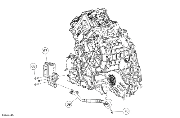
Understanding the 2014 Ford Escape's transmission is crucial for anyone looking to perform maintenance, troubleshoot issues, or even consider performance modifications. This article breaks down the transmission diagram, equipping you with the knowledge to confidently navigate its complexities. We'll cover key components, how they function, and provide real-world troubleshooting advice.
Purpose of the Transmission Diagram
The transmission diagram is essentially a roadmap of the transmission's internal workings. It serves multiple purposes:
- Diagnostics: Identifying the location of components when diagnosing problems. A diagram helps pinpoint the source of a leak, noisy bearing, or malfunctioning sensor.
- Repair and Overhaul: Guiding the disassembly and reassembly process during repairs or a complete rebuild. Knowing the order of operations and the location of all parts is paramount.
- Understanding Operation: Gaining a deeper understanding of how the transmission works. This knowledge is invaluable for troubleshooting unusual behavior or considering performance upgrades.
- Parts Identification: Ensuring you order the correct replacement parts. Diagrams often have part numbers or at least precise depictions of the component's shape and size.
Key Specs and Main Parts (6F35 Transmission)
The 2014 Ford Escape predominantly uses the 6F35 automatic transmission. This is a six-speed transaxle, meaning it integrates the transmission and differential into a single unit. Some models may have used other transmissions, but the 6F35 is the most common. Knowing the specific transmission model is critical, as diagrams vary. This article primarily focuses on the 6F35.
Here are some key specs and the main parts you'll encounter in the diagram:
- Type: 6-speed automatic transaxle
- Gear Ratios: Vary depending on engine and trim level, but generally range from approximately 4.15 (1st gear) to 0.69 (6th gear).
- Torque Converter: A fluid coupling that transmits engine torque to the transmission input shaft. Includes a stator and turbine. Critical for smooth starts and torque multiplication.
- Valve Body: The "brain" of the transmission. Contains a complex network of hydraulic valves, solenoids, and channels that control gear selection based on inputs from the Transmission Control Module (TCM).
- Solenoids: Electrically controlled valves that open and close hydraulic circuits within the valve body to engage different gears. Common failure points in automatic transmissions.
- Clutch Packs and Bands: Friction materials that engage and disengage different gear sets to achieve different gear ratios. Subject to wear and tear over time.
- Planetary Gear Sets: A system of gears (sun gear, planet gears, ring gear) that multiplies torque and changes gear ratios.
- Transmission Control Module (TCM): A computer that monitors sensors and controls the solenoids in the valve body. Receives inputs from the engine control unit (ECU) and other sensors.
- Oil Pump: Provides hydraulic pressure to operate the valve body, clutches, and torque converter.
- Differential: Allows the wheels to rotate at different speeds when turning.
Understanding the Symbols in the Diagram
Transmission diagrams use a variety of symbols to represent different components and connections. Here's a breakdown of common symbols you'll encounter:
- Solid Lines: Typically represent hydraulic lines, carrying transmission fluid under pressure. Varying thicknesses may indicate different line sizes or pressure levels.
- Dotted Lines: Often represent electrical wiring or signal paths. May connect sensors to the TCM or the TCM to solenoids.
- Color Coding: Some diagrams use color coding to identify different fluid circuits or electrical connections. For example, blue might represent the main pressure line, while green could represent a specific clutch apply circuit. Always refer to the diagram's legend.
- Boxes and Rectangles: Generally represent valves, solenoids, or other control components. Internal markings within the box may indicate the valve type or its function.
- Circles: May represent gears, bearings, or other rotating components.
- Arrows: Indicate the direction of fluid flow or electrical signal.
- Ground Symbols: Indicate a connection to the vehicle's ground.
A thorough examination of the diagram's legend or key is crucial to properly interpret these symbols.
How the 6F35 Transmission Works (Simplified)
The 6F35 transmission uses a combination of planetary gear sets, clutches, and bands to achieve six forward gears and one reverse gear. The torque converter transmits power from the engine to the transmission input shaft. The valve body, controlled by the TCM, directs hydraulic pressure to engage and disengage specific clutches and bands. By selectively engaging these clutches and bands, different gear ratios are achieved within the planetary gear sets. The TCM uses inputs from various sensors (wheel speed, throttle position, engine speed) to determine the optimal gear for current driving conditions.
In essence, the TCM is the "brain" that decides when and how to shift, while the valve body and its associated hydraulic system are the "muscles" that execute those shifts.
Real-World Use: Basic Troubleshooting Tips
Here's how you can use the transmission diagram to troubleshoot common problems:
- Fluid Leaks: Use the diagram to identify potential leak points. Follow the hydraulic lines and look for connections, seals, or cracked housings. Common leak areas include the torque converter seal, valve body gaskets, and cooler lines.
- Shifting Problems: If the transmission is slipping, shifting hard, or not shifting at all, the diagram can help you pinpoint the potential culprit. For example, if a specific gear is not engaging, you can trace the hydraulic circuit for that gear back to the valve body and check the corresponding solenoid. Check the solenoid resistance with a multimeter according to service manual specification.
- Diagnostic Trouble Codes (DTCs): If the TCM has stored a DTC related to the transmission, the diagram can help you understand the code's meaning and identify the relevant components. For example, a code related to a specific solenoid can be traced on the diagram to locate and test that solenoid.
- Noise: Use the diagram to identify potential sources of noise. Noises such as whine may indicate a failing oil pump. Check oil pump based on the diagram schematic for functionality and pressure.
Important Note: Always consult the factory service manual for specific diagnostic procedures and torque specifications. A transmission diagram is a helpful tool, but it's not a substitute for proper training and experience.
Safety Considerations
Working on a transmission involves several safety risks:
- High Pressure Fluids: The transmission operates with high-pressure fluids. Always relieve pressure before disconnecting any lines. Transmission fluid can be hot and can cause burns.
- Heavy Components: The transmission is heavy and can cause injury if dropped. Use proper lifting equipment and support stands.
- Electrical Hazards: The TCM and solenoids operate on electrical power. Disconnect the battery before working on any electrical components.
- Moving Parts: Never operate the transmission with the inspection cover removed or with your hands near moving parts.
- Chemicals: Transmission fluid contains chemicals that can be harmful if ingested or come into contact with skin. Wear appropriate gloves and eye protection.
- Torque Converter: Torque converter contains fluid. Be careful when handling, and avoid damaging the snout of the transmission or torque converter.
Warning: Mishandling the high-pressure circuits or electrical components can result in serious injury or damage to the transmission.
We have a detailed 2014 Ford Escape transmission diagram available for download. This diagram provides a comprehensive view of the transmission's internal workings, including hydraulic circuits, electrical connections, and component locations. This is an invaluable resource for anyone undertaking repairs or modifications.