
2014 Ford F150 Exhaust System Diagram
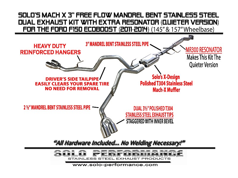
Alright, let's dive into the exhaust system of the 2014 Ford F-150. This article is going to break down the exhaust system diagram, explaining the components, their function, and how to interpret the diagram itself. Whether you're tackling a repair, planning a modification, or just want to understand your truck better, a solid understanding of the exhaust system is crucial.
Why You Need This Diagram
Having the exhaust system diagram for your 2014 F-150 is like having a roadmap for one of the truck's most important systems. It's invaluable for:
- Troubleshooting: Identifying faulty components quickly.
- Repairing: Knowing where parts are located and how they connect.
- Modifying: Planning aftermarket upgrades like cat-back systems or headers.
- Understanding: Gaining a deeper knowledge of your vehicle's operation.
Without the diagram, you're essentially working blind. You might replace the wrong part, causing further damage, or struggle to correctly reinstall components after removal. This guide and the accompanying diagram provide the clarity you need to work efficiently and effectively.
Key Specs and Main Parts of the 2014 F-150 Exhaust System
The 2014 F-150 came with a variety of engine options, each having slightly different exhaust system configurations. We'll focus on the common elements, but be aware that variations exist depending on your specific engine (3.7L V6, 5.0L V8, 3.5L V6 EcoBoost, or 6.2L V8).
Exhaust Manifolds/Headers
These are the starting point of the exhaust system, bolted directly to the engine cylinder heads. Their job is to collect the exhaust gases from each cylinder. Headers, often aftermarket, offer improved flow compared to the stock cast iron manifolds.
Catalytic Converters
These are essential for emissions control. They use chemical reactions to convert harmful pollutants (hydrocarbons, carbon monoxide, and nitrogen oxides) into less harmful substances. The 2014 F-150 typically has two or more catalytic converters depending on the engine. They are a common source of problems, especially if the engine is running rich or burning oil.
Oxygen Sensors (O2 Sensors)
Located before (upstream) and after (downstream) the catalytic converters, O2 sensors monitor the oxygen content in the exhaust gas. This data is sent to the engine control unit (ECU) to fine-tune the air-fuel mixture. Faulty O2 sensors can lead to poor fuel economy, rough running, and emissions failures.
Muffler
The muffler reduces the noise produced by the engine. It uses a series of chambers and baffles to dampen sound waves. Different mufflers can provide different sound characteristics, from quiet stock replacements to loud performance models.
Tailpipe
The tailpipe is the final section of the exhaust system, routing the exhaust gases away from the vehicle. It's often visible at the rear of the truck.
Resonator (Sometimes Present)
Some models may have a resonator, an additional sound-dampening device located before the muffler. It's designed to cancel out specific frequencies and further reduce noise and drone.
Exhaust Pipes
These are the connecting pipes that link all the components together. They are typically made of steel or aluminized steel. Common sizes are 2.5" or 3" depending on the application.
Hangers and Mounting Points
These are essential for supporting the exhaust system and preventing it from rattling or vibrating against the chassis. Inspect these regularly for corrosion or damage.
Understanding the Diagram: Symbols and Conventions
The exhaust system diagram uses standardized symbols and conventions to represent the various components and their relationships. Here's a breakdown:
- Solid Lines: Represent physical pipes or connections between components. The thickness of the line may indicate pipe diameter.
- Dotted Lines: Often represent vacuum lines or electrical connections, especially for O2 sensors.
- Component Symbols: Each component (catalytic converter, muffler, etc.) has a specific symbol. Catalytic converters are often depicted as rectangular boxes with internal structures, mufflers as elongated cylinders, and O2 sensors as circles with wiring coming out.
- Arrows: Indicate the direction of exhaust gas flow.
- Mounting Points: Represented by small triangles or circles, showing where the system is attached to the vehicle's chassis.
- Labels: Each component is labeled with a code or name, allowing you to identify it precisely. Refer to the diagram's legend for the meaning of each code.
Some diagrams might use color-coding, although this is less common in basic exhaust diagrams. If colors are used, a legend will explain their meaning (e.g., red for hot exhaust gases, blue for cooling air).
How the 2014 F-150 Exhaust System Works
The process starts with the engine's combustion cycle. Exhaust gases are expelled from the cylinders into the exhaust manifolds or headers. From there, the gases flow into the catalytic converters, where harmful pollutants are reduced. The O2 sensors monitor the effectiveness of this process and provide feedback to the ECU.
After the catalytic converters, the exhaust gases travel through the muffler (and potentially a resonator) to reduce noise. Finally, the gases exit the vehicle through the tailpipe.
The entire system is designed to efficiently remove exhaust gases, minimize pollution, and reduce noise levels. The ECU constantly monitors the system's performance through the O2 sensors, adjusting the engine's parameters to optimize combustion and emissions.
Real-World Use: Basic Troubleshooting
Here are a few common exhaust system problems and how the diagram can help you diagnose them:
- Exhaust Leak: A hissing or roaring sound, often accompanied by a smell of exhaust fumes. The diagram helps you identify potential leak locations, such as flanges, welds, or cracked pipes. Visually inspect these areas for signs of soot or damage.
- Catalytic Converter Failure: Indicated by a check engine light (CEL) with codes like P0420 or P0430. The diagram shows the location of the converters, allowing you to visually inspect them for damage or deterioration. A scan tool is needed to read the codes.
- O2 Sensor Failure: Also indicated by a CEL. The diagram shows the location and type of each O2 sensor (upstream or downstream). Use a multimeter to test the sensor's resistance and voltage.
- Rattling Noise: Could be a loose exhaust hanger or a component hitting the chassis. The diagram helps you locate the hangers and mounting points.
Important: Always allow the exhaust system to cool down completely before working on it. Burns are a common injury when working on exhaust systems.
Safety Considerations
Working on an exhaust system can be dangerous. Here are some key safety points:
- Hot Surfaces: The exhaust system gets extremely hot. Allow it to cool down completely before touching any components.
- Exhaust Fumes: Exhaust fumes are toxic. Work in a well-ventilated area, and consider using a respirator.
- Lifting the Vehicle: Always use proper jack stands when working under a vehicle. Never rely solely on a jack.
- Rust and Corrosion: Exhaust systems are prone to rust. Wear gloves to protect your hands from sharp edges and tetanus.
- O2 Sensors: When replacing O2 sensors, disconnect the negative battery cable to prevent electrical shorts.
- Catalytic Converters Catalytic Converters contain precious metals and should be handled with care. When replacing, dispose of the old converter properly. Never tamper or remove a catalytic converter if you are not certified to do so.
This information provides a comprehensive guide to understanding the 2014 Ford F-150 exhaust system diagram. Remember to consult the specific diagram for your engine configuration. We have the file, and you can download the detailed diagram for the 2014 Ford F-150 exhaust system to assist you further with your projects. This will make your repair, modification, or learning experience easier and more efficient. Always prioritize safety and consult a professional if you are unsure about any aspect of the work.