2014 Freightliner Cascadia Fuse Box Diagram
Okay, let's dive into the often-intimidating, but absolutely crucial, world of the 2014 Freightliner Cascadia's fuse box. Whether you're troubleshooting an electrical gremlin, planning a modification, or just expanding your understanding of your rig, knowing your way around the fuse boxes is essential. This guide is designed to give you a solid understanding of the system, empowering you to tackle basic electrical issues with confidence.
Purpose of the Fuse Box Diagram
Think of the fuse box diagram as the roadmap to your truck's electrical nervous system. It serves several vital purposes:
- Troubleshooting: When a circuit fails (lights out, wipers dead, etc.), the diagram helps you quickly locate the corresponding fuse and determine if it's blown. This saves time and prevents unnecessary diagnostics.
- Modification and Add-ons: Planning to install auxiliary lights, a CB radio, or an upgraded sound system? The diagram allows you to identify suitable circuits for tapping power, ensuring you don't overload existing systems or accidentally tap into something critical.
- General Understanding: Even if everything is working perfectly, studying the diagram gives you a deeper appreciation of how your truck's electrical system is organized. This knowledge can be invaluable in the long run.
- Repair and Maintenance: Sometimes components may require repairs, and the diagram can help pinpoint the location of components and their corresponding fuses.
Key Specs and Main Parts
The 2014 Cascadia typically has multiple fuse boxes. Understanding their location and general function is the first step:
- Under-Dash Fuse Box (Driver's Side): This is often the primary fuse box, housing fuses for interior lighting, instrument panel functions, radio, and other cabin-related circuits.
- Under-Hood Fuse Box (Engine Compartment): This box typically contains fuses and relays for engine management systems, headlights, cooling fans, and other critical vehicle functions. It may also include high-amp fuses like those for ABS or main power distribution.
- Sleeper Compartment Fuse Box (If Equipped): If your Cascadia has a sleeper, there's likely a dedicated fuse box for managing power to interior lights, outlets, and other sleeper-specific accessories.
Important Specs:
- Voltage: Primarily 12V DC (Direct Current). Knowing this is critical when choosing fuses and wiring for aftermarket accessories.
- Fuse Ratings: Fuses are rated in Amps (A). These ratings are absolutely critical, so replacing a fuse with the correct amperage is crucial for safety.
- Relay Types: The fuse box also houses relays, which are electrically operated switches. Relays are used to control high-current circuits with low-current signals.
Symbols, Lines, Colors, and Icons
Understanding the symbology on the fuse box diagram is key to using it effectively. While specific diagrams can vary slightly, here are common elements:
- Lines: Solid lines generally represent wiring connections. Dashed lines may indicate ground connections or shielded wiring.
- Colors: Wire colors are often indicated on the diagram (e.g., BLK for Black, RED for Red, GRN for Green). This helps you trace wires in the actual harness.
- Icons: Icons represent specific components like headlights, wipers, the radio, or various control modules. Common icons include:
- A headlight icon for headlight circuits.
- A windshield wiper icon for the wiper motor circuit.
- A radio speaker icon for the radio.
- A battery icon for the power supply.
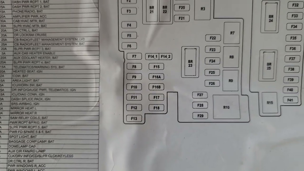
- Numbers/Labels: Each fuse and relay location is typically labeled with a number or alphanumeric code. These codes are used to identify the circuit protected by that fuse or controlled by that relay. The legend associated with the fuse box diagram cross-references the fuse number with its function.
Example: A label might read "F23 - Instrument Panel Lights (10A)". This means fuse number 23 protects the instrument panel lights and is rated at 10 Amps.
How It Works: A Simplified Explanation
The electrical system works like a network of interconnected circuits, each powered by the battery and protected by a fuse. When a circuit draws too much current (usually due to a short circuit or an overload), the fuse's internal filament melts, breaking the circuit and preventing damage to wiring and components. This is why fuses are considered a sacrificial element.
Relays act as electrically controlled switches. A small current through the relay's coil closes a set of contacts, allowing a much larger current to flow through a separate circuit. This is used to control high-power devices like headlights or starter motors without running high-current wiring to the switch in the cab.
The fuse box diagram is literally a schematic representation of these circuits. It shows the connections, fuse locations, and relay assignments, making it possible to trace the path of electricity from the battery to the various components.
Real-World Use: Basic Troubleshooting Tips
Here's how to use the fuse box diagram for basic troubleshooting:
- Identify the Problem: What's not working? Be specific (e.g., "left headlight is out").
- Consult the Diagram: Locate the fuse or relay associated with the non-functional component. The diagram might be printed on the fuse box cover, or it might be a separate document.
- Inspect the Fuse: Visually check the fuse. If the filament is broken, the fuse is blown. You can also use a multimeter to test for continuity across the fuse terminals. If there is no continuity, the fuse is blown.
- Replace the Fuse: Replace the blown fuse with a new fuse of the exact same amperage rating. Using a higher-rated fuse can create a fire hazard.
- Test: After replacing the fuse, test the circuit to see if the problem is resolved. If the fuse blows again immediately, there's likely a short circuit in the wiring or the component itself. Further investigation is needed.
- Relay Testing: If a component isn't working, and the fuse is good, the relay may be faulty. Relays can be tested with a multimeter, but it often requires knowledge of relay operation. Swapping with an identical relay from a less critical circuit is a quick test (e.g., swapping the horn relay with the fog light relay).
Safety Considerations
Working with electrical systems can be dangerous. Here are some crucial safety precautions:
- Disconnect the Battery: Before working on any electrical component, disconnect the negative terminal of the battery. This prevents accidental shorts and electrical shocks.
- Use Proper Tools: Use insulated tools designed for electrical work.
- Never Exceed Fuse Ratings: Always replace a blown fuse with a fuse of the correct amperage rating. Using a higher-rated fuse can damage wiring and components, and it can create a fire hazard.
- Be Aware of High-Current Circuits: Be particularly cautious around high-current circuits like those for the starter motor, alternator, and ABS system. These circuits can deliver a significant electrical shock.
- Capacitors: Some circuits contain capacitors that can store an electrical charge even after the battery is disconnected. Allow sufficient time for capacitors to discharge before working on these circuits.
- When in Doubt, Consult a Professional: If you're not comfortable working on the electrical system, or if you suspect a serious problem, take your truck to a qualified mechanic.
Understanding your 2014 Freightliner Cascadia's fuse box is a valuable skill. Remember to prioritize safety, use the correct tools, and always refer to the appropriate diagram. With a little knowledge and caution, you can confidently diagnose and repair many common electrical issues.
We have the full 2014 Freightliner Cascadia Fuse Box Diagram file available for download. This detailed diagram will be an invaluable resource for your troubleshooting and modification projects. Feel free to download it and keep it handy for future reference.