2014 Nissan Murano Fuse Box Diagram
So, you're diving into the electrical system of your 2014 Nissan Murano? Smart move! Understanding the fuse box diagram is crucial for anything from diagnosing a simple blown fuse to tackling more complex electrical modifications. This guide will break down everything you need to know, helping you navigate your Murano's electrical heart with confidence.
Purpose of the Fuse Box Diagram
Why bother with this diagram? The fuse box diagram is your roadmap to your car's electrical circuits. Without it, you're essentially poking around in the dark. Its main purposes include:
- Troubleshooting Electrical Issues: Identifying which fuse corresponds to a specific component (lights, radio, power windows, etc.) allows you to quickly pinpoint the source of a problem. A blown fuse is often the culprit behind a malfunctioning system.
- Performing Repairs: Once you've identified a faulty fuse, the diagram confirms its amperage rating, ensuring you replace it with the correct one. Using the wrong amperage can lead to further damage or even a fire.
- Making Modifications: Planning to install aftermarket accessories like a subwoofer, auxiliary lights, or a dashcam? The fuse box diagram helps you locate suitable power sources and tap into the electrical system safely and efficiently.
- General Understanding: Even if you don't have immediate issues, studying the diagram provides a valuable overview of your car's electrical architecture. It helps you understand how different systems are interconnected.
Key Specs and Main Parts
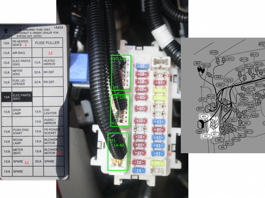
The 2014 Nissan Murano typically has two main fuse box locations:
- Interior Fuse Box: Usually located under the dashboard on the driver's side, near the steering column. This fuse box houses fuses for interior components like the radio, lights, power windows, and climate control.
- Engine Compartment Fuse Box: Situated in the engine bay, often near the battery. This fuse box contains fuses and relays for critical engine components like the fuel pump, ignition system, and cooling fans. It may also contain fuses for exterior lighting.
Each fuse box contains the following key components:
- Fuses: These are the sacrificial lambs of your electrical system. They're designed to break the circuit (blow) if the current exceeds a safe level, protecting more expensive components from damage. They come in various amperage ratings (e.g., 5A, 10A, 15A, 20A, 30A). Common fuse types are blade fuses (ATO/ATC) and mini-blade fuses.
- Relays: These are electrically operated switches that control high-current circuits using a low-current signal. Relays are used to activate components like headlights, starter motors, and fuel pumps.
- Fuse Box Housing: The physical container that holds the fuses and relays. It's usually made of plastic and provides protection from the elements.
- Fuse Puller: A small plastic tool used to safely remove fuses without damaging them. It's typically included in the fuse box or with your car's toolkit.
Understanding the Symbols on the Diagram
Fuse box diagrams use a combination of lines, colors, and icons to represent different circuits and components. Here's a breakdown of common symbols:
- Solid Lines: Represent electrical wires or connections. A thicker line may indicate a wire carrying a higher current.
- Dotted Lines: Often indicate ground connections or less critical connections.
- Colors: Wire colors are usually indicated on the diagram to help you trace circuits. Common colors include red (positive), black (ground), blue, yellow, green, and white.
- Icons: Represent specific components, such as:
- Lightbulb: Indicates a lighting circuit (headlights, taillights, interior lights).
- Speaker: Indicates the audio system (radio, speakers).
- Motor: Indicates a motor-driven component (power windows, power seats, windshield wipers).
- Coil/Resistor symbol: Indicates a relay.
- Amperage Ratings: Numbers next to the fuse symbols indicate the amperage rating of that particular fuse (e.g., 15A). Always replace a blown fuse with one of the same amperage rating!
How It Works: A Simplified Explanation
The electrical system of your Murano is a network of circuits, each designed to power a specific component or group of components. Electricity flows from the battery, through the wiring, and to the components. Fuses are strategically placed within these circuits to protect them from overcurrent. When a fault occurs (e.g., a short circuit), the current flowing through the fuse exceeds its amperage rating, causing the fuse to melt and break the circuit. This prevents the excessive current from damaging other components. Relays are used to control high-current circuits using low-current signals. For example, the switch you use to turn on your headlights only controls a small current that activates the relay. The relay then closes the circuit, allowing a much larger current to flow to the headlights.
Think of it like a water pipe with a weak point. If the water pressure gets too high, the weak point bursts, preventing the entire pipe system from being damaged.
Real-World Use: Basic Troubleshooting Tips
Here are some basic troubleshooting steps using the fuse box diagram:
- Identify the Problem: Determine which component is not working (e.g., the radio, the headlights, the power windows).
- Consult the Diagram: Locate the fuse that corresponds to the malfunctioning component in the fuse box diagram. Refer to both interior and engine compartment fuse box diagrams.
- Inspect the Fuse: Using the fuse puller, carefully remove the fuse and visually inspect it. A blown fuse will have a broken filament or a darkened appearance.
- Replace the Fuse: If the fuse is blown, replace it with a new fuse of the exact same amperage rating.
- Test the Component: Turn on the component to see if it now works. If the fuse blows again immediately, there is likely a more serious problem in the circuit, such as a short circuit. Do not keep replacing the fuse; seek professional help.
- Check the Relay (if applicable): If the fuse is good but the component still doesn't work, the relay might be faulty. Relays can be tested using a multimeter, but this requires some electrical knowledge. If you're unsure, consult a mechanic.
Safety: Highlighting Risky Components
Working with electrical systems can be dangerous. Here are some safety precautions:
- Disconnect the Battery: Before working on any electrical system, disconnect the negative terminal of the battery. This will prevent accidental shocks or short circuits.
- Use the Right Tools: Use insulated tools designed for electrical work.
- Never Exceed Amperage Ratings: Always replace a blown fuse with one of the same amperage rating. Using a higher amperage fuse can overload the circuit and cause a fire.
- Be Careful with Relays: Relays control high-current circuits. Be cautious when working with them.
- Avoid Water: Never work on electrical systems in wet conditions.
- If in Doubt, Seek Professional Help: If you're not comfortable working with electrical systems, consult a qualified mechanic.
- SRS System: The SRS (Supplemental Restraint System) or airbag system is a high-risk component. Improper handling can lead to accidental airbag deployment, causing serious injury. Never attempt to repair or modify the SRS system yourself. Consult a qualified technician. The fuse for the SRS system should only be removed by a professional.
Remember, safety is paramount when working on your car's electrical system.
We have a high-resolution, printable PDF file of the 2014 Nissan Murano fuse box diagram. You can download it [here - insert link to downloadable file here]. This will be a valuable resource as you work on your Murano.